Overview
Mesh Setting Overview #
This section describes mesh settings in the solver.
Mesh is one of the most critical settings in a solver, directly impacting simulation accuracy and computational efficiency. Proper mesh partitioning can effectively balance computational resources and simulation accuracy, avoiding numerical errors and resource waste.
The following sections describe the three mesh types supported by the FDTD solver. Only the FDTD solver fully supports all three types. Mesh settings in FDFD, FDE, EME, and FDCharge are similar to semi-auto nonuniform mesh. The RCWA solver provides auto / custom mesh types that are similar to uniform mesh.
Uniform Mesh #
In a uniform mesh (Uniform), each mesh cell has the same size. This type is suitable for simple structures with smooth variations, enabling quick simulations and debugging. It is ideal for most standard simulation scenarios. The FDTD solver supports this mesh type; the RCWA solver's auto / custom mesh types are similar in partitioning behavior. Uniform mesh requires Mesh definition type, supporting Mesh size and Number of mesh cells.
Auto Nonuniform Mesh #
Auto nonuniform mesh (Auto nonuniform) automatically generates nonuniform meshes based on the user-defined Accuracy level to improve simulation accuracy and computational efficiency. It is recommended for most complex structures, especially multi-scale problems. This is the default mesh type for the FDTD solver and is supported only by FDTD. Auto nonuniform mesh does not use Mesh definition type; mesh partitioning is controlled automatically by the accuracy level.
Semi-auto Nonuniform Mesh #
Semi-auto nonuniform mesh (Semi-auto nonuniform) allows users to customize local mesh sizes to meet specific simulation needs. It is suitable for complex structures where certain regions require higher accuracy, and requires users to have some experience in mesh settings. The FDTD solver supports this mesh type. FDFD, FDE, EME, and FDCharge do not offer the semi-auto nonuniform mesh type name, but their mesh settings work in a similar way; refer to this section for parameter guidance. Semi-auto nonuniform mesh requires Mesh definition type and supports all four definition methods.
Mesh Refinement #
Mesh refinement improves calculation accuracy at material interfaces, including staircase and conformal methods and mesh refinement subcells.
Minimum Mesh Size #
Min mesh size setting sets the lower limit on mesh cell size allowed by the software during mesh generation. Regardless of the mesh type selected, no generated cell will be smaller than this value. In general, a smaller minimum mesh size provides finer resolution but requires more computational resources. This parameter does not need to be modified under normal conditions.
| Name | Default | Description |
|---|---|---|
| Min mesh size setting | 0.00025 μm | Defines the minimum mesh cell size allowed by the software. |
Time Step Size #
Time step settings are specific to the FDTD solver and relate to numerical stability conditions for the time-stepping scheme. Other algorithms such as FDFD, FDE, EME, FDCharge, and RCWA do not include this setting.
| Name | Default | Description |
|---|---|---|
| Stability factor | 0.99 | The ratio between the maximum allowable step size of each time step and the actual time step size used. This parameter determines if the time step size is small enough to maintain numerical stability and accuracy. |
| dt | - | Time step size, a read-only parameter. |
Mesh Order #
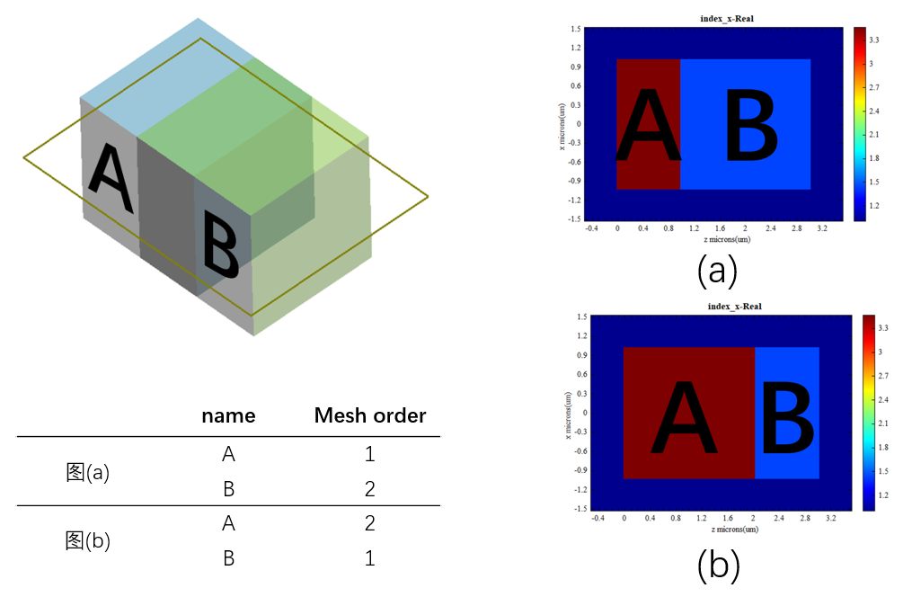
Mesh order is a structural property used to set the order in which meshes are created. This property applies to all mesh types described above.
When structures overlap in space, the selection of materials for the overlapping region can be controlled by setting the Mesh order (the larger the Mesh order, the higher the material grade). The specific setting steps are as follows: select a structure, right-click to open the Edit properties window, switch to the Material tab, tick Override mesh order (inactivated by default), and set the number of levels for Mesh order.
By modifying the Mesh order for structure A and structure B, the material selection for the intersecting space is specified, as shown in the figure below.