Auto Nonuniform Mesh
Auto Nonuniform Mesh #
This section describes auto nonuniform mesh (Auto nonuniform) settings in the solver. For an overview of mesh types, see Mesh Setting Overview.
Auto nonuniform mesh automatically generates nonuniform meshes based on the user-defined Accuracy level to improve simulation accuracy and computational efficiency. It is recommended for most complex structures, especially multi-scale problems, automatically balancing accuracy and computational cost. This is the default mesh type for the FDTD solver and is supported only by FDTD.
Auto nonuniform mesh does not use Mesh definition type. Unlike uniform and semi-auto nonuniform mesh, mesh partitioning in each direction is determined automatically by the accuracy level based on wavelength and material refractive index. Users do not need to specify the definition method for the X, Y, and Z directions separately.
Accuracy Level #
When the mesh type is set to Auto nonuniform, the Accuracy level must be configured. The accuracy level ranges from 1 (coarsest) to 10 (finest), expressed as
N=nΔλ0
where λ0 is the wavelength in vacuum, n is the refractive index of the material, and Δ is the mesh size.
This equation shows that mesh partitioning depends on wavelength and material refractive index. For example, in vacuum, an accuracy level of 1 divides one wavelength into 6 mesh cells, level 2 into 10 cells, and so on, increasing by 4 cells per level. In high-refractive-index materials, smaller meshes are used. Finer mesh partitioning reduces numerical dispersion but significantly increases computational speed and resource requirements. We recommend users balance their specific project needs and available resources to select an appropriate accuracy level. For most simulations, an accuracy level of 2–5 is sufficient.
For mesh refinement, see Mesh Refinement. For minimum mesh size, time step, and Mesh order, see Mesh Setting Overview.
Case Study: Coaxial Antenna Mesh Settings #
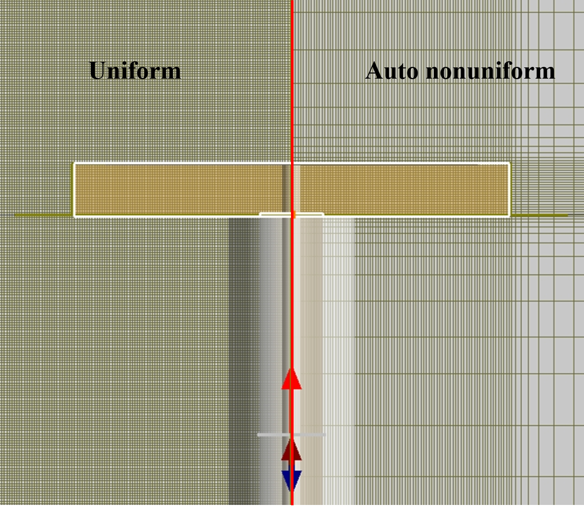
A coaxial antenna contains a metal conductor and a dielectric fill, making it a typical structure for demonstrating auto nonuniform mesh partitioning. With auto nonuniform mesh selected, the software determines the mesh size in each region automatically based on the Accuracy level: smaller cells are generated near conductor–dielectric interfaces and in regions with higher refractive index or concentrated geometric detail, while lower-refractive-index regions (such as the outer vacuum) use a relatively coarser mesh. This preserves accuracy in critical areas while reducing the total cell count and simulation time.
The figure below compares uniform mesh and auto nonuniform mesh for the same coaxial antenna model. Uniform mesh keeps the same cell size throughout the simulation region, including relatively dense partitioning in the outer vacuum. Auto nonuniform mesh adaptively refines around the structure and remains sparse in outer regions, improving overall computational efficiency.