Structures
Structures #
This section is an introduction to structures.
The software supports the 3D Computer Aided Design (CAD). See CAD.
Users can add and modify structures through script in the software. Please refer to Script.
Structures #
Structure and Project #
A simulation should include a structure and a solution algorithm.
Structure is the basic unit of a simulation. The software provides rich structures and structure groups.
Structure Creation #
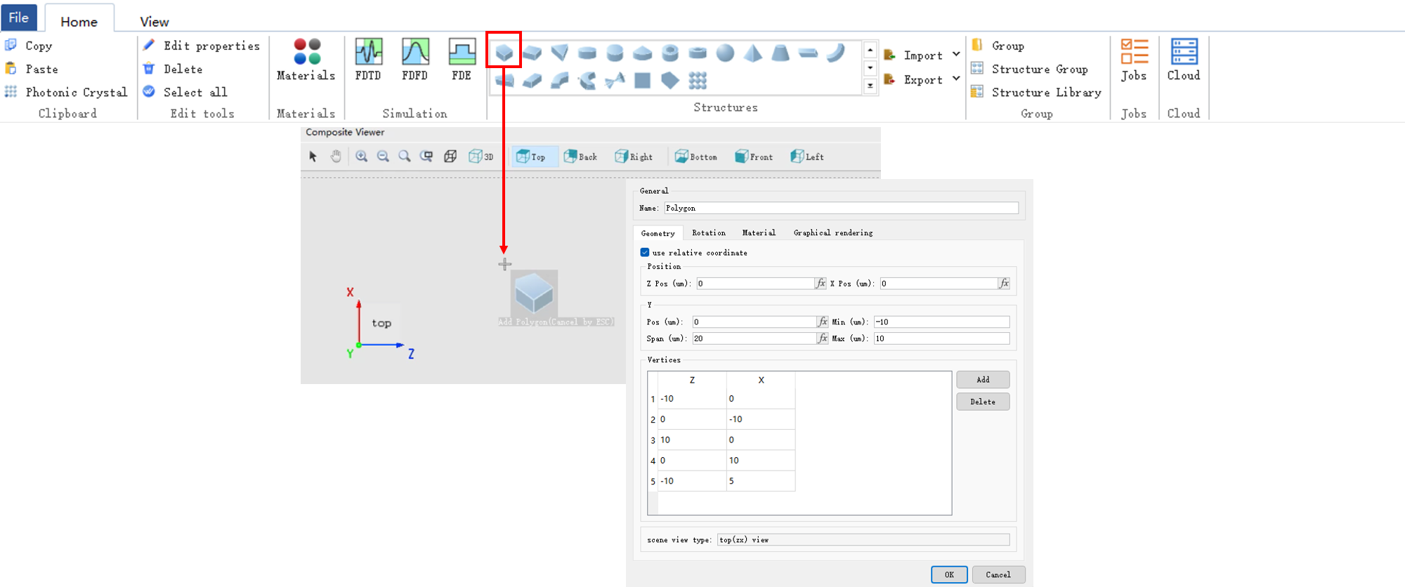
- In the Structure area of the Home tab, all available structures are included.
- Select the desired structure and click anywhere within the Composite viewer window.
- Make the appropriate settings in the pop-up Edit Structure Properties window to finalize the creation.
Structure Settings #
Geometry Size Settings #
The Geometry tab is used to set the geometry size of the structure.
| Name | Description |
|---|---|
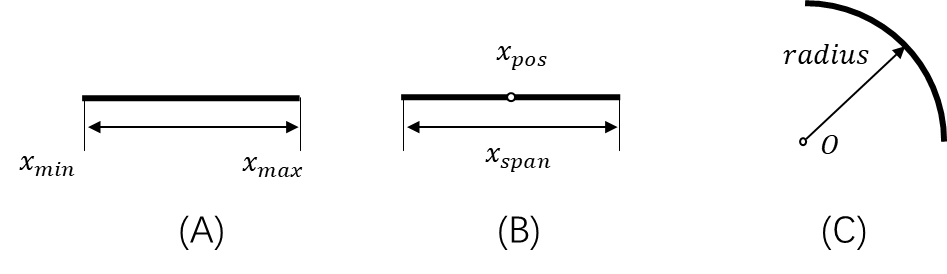
| X/Y/Z pos | Set the structure center. |
| X/Y/Z span | Set the structure scope. |
| Radius X/Y/Z | Set the radius X/Y/Z of the structure. |
| Scene view type | It determines the structure creation direction. |
Rotation Settings #
The Rotation tab is used to set the structure rotation.
| Name | Description |
|---|---|
| Rotation axis | Set the rotation axis. The rotation axis is the normal vector of the rotation plane. |
| Rotation | Enter the rotation angle (unit: degree). |
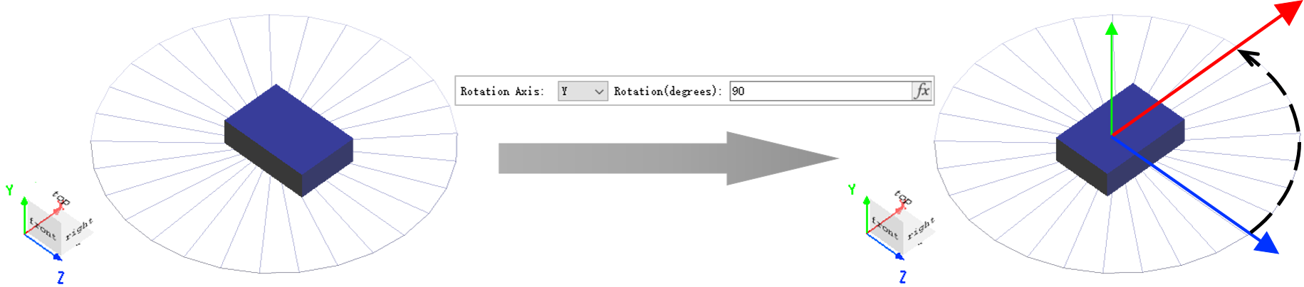
In the world coordinate system of the composite viewer, the forward direction of the coordinate axis is the forward direction of the normal vector of the rotation plane.
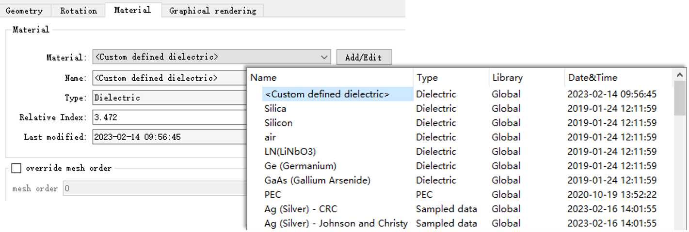
Material Setting #
The Material tab is used to set the structure material. The structure without material does not exist (the default material is given at the beginning of the creation of the structure). See Dielectric.
| Name | Description |
|---|---|
| Material | Drop-down menu. Select the structure material. |
| Add/Edit | Add/Edit project materials. |
| Override mesh order | Start mesh level input. |
| Mesh order | Mesh level. Set the order to create mesh. |
The rest items of the default material such as Name, Type, etc. are automatically filled in, which are view-only items.
Graphics Rendering Setting #
The Graphical rendering tab is used to set the opacity and rendering precision of the structure.
| Name | Description |
|---|---|
| Override default transparency | Select and set the material opacity. |
| Opacity | Set the material opacity: 1: opacity; 0: transparency. |
| Detail points | The rendering accuracy of the structure in the 3D display. The higher the accuracy, the more detailed the rendering effect. |
Built-in Structures and Structure Group #
Built-in Structure #
The following table lists the structure types that are supported by the software:
| Name | Description |
|---|---|
| Polygon class | Polygon, Rectangle, Triangle. |
| Polygon 2D class | Polygon2D, Rectangle2D. |
| Ellipse class | Ellipse, Circle, Sector. |
| Ring class | Circle ring, Ellipse ring. |
| Sphere | Ball. |
| Pyramid class | Pyramid, Cone. |
| Linear Taper | Linear taper class, used to construct transition structures with waveguide cross-sections that change linearly along the length. |
| Sidewall class | Sidewall linear, Sidewall arc, Sidewall bezier. |
| Waveguide class | Linear waveguide, Arc waveguide, Linear taper. |
| Equation | Use the analytic expressions to build a 2D outline of the structure, and then form a 3D structure through rotation or stretch. |
| Photonic Crystal | Photonic crystal structure, which can be used to construct various lattices such as square and hexagonal. |
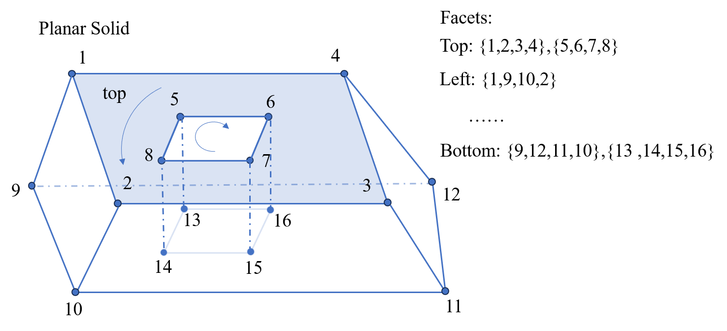
| Planar Solid | Planar solid structure, which can be viewed as a 3D extension of a polygon. Complex 3D geometries are created by defining vertex coordinates and facet indices. |
| Surface | Surface class, used to construct continuous surface structures, with support for setting the top and bottom surfaces. |
Special types to note:
- Planar Solid
Except for Planar Solid, the parameters of all other structures can be edited and set via the property panel. For Planar Solid structures, the vertices and facets variables must be defined via script. Users can either use the addplanarsolid command to add one directly or set the parameters using the set command.
Creating a Planar Solid requires defining two key variables:
vertices: Vertex coordinate matrix. Each row represents the (x, y, z) coordinates of a vertex.facets: Facet indices, defining which vertices enclose each face. This variable can be a matrix or a cell array. The order of vertex indices must follow the right-hand rule to determine the front (positive) and back (negative) sides of the face (e.g., in the figure, vertices 1→2→3→4 form a positive face, while vertices 5→6→7→8 form a negative face).
If these two variables are not defined, a rectangular structure is created.
- Surface
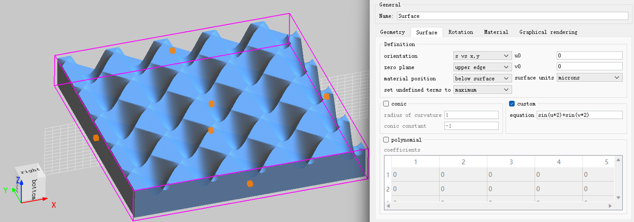
The principle of the Surface structure is essentially the same as that described in Importing Surface Structures. It can also be added directly from the built-in structure library. The settings page is shown below:
| Name | Description |
|---|---|
| orientation | Selects the coordinate plane on which the surface S depends: the surface is defined as z = S(x,y) (s vs x,y), y = S(x,z) (s vs x,z), or x = S(y,z) (s vs y,z). |
| zero plane | Determines the reference for measuring the surface height: upper edge means the height is measured from the top edge of the rectangular volume; lower edge means from the bottom edge. |
| material position | Determines which side of the surface is filled with material: below surface fills the region below the surface; above surface fills the region above the surface. |
| set undefined terms to | When the surface equation is undefined at some (u,v), the surface function is set to either maximum (the maximum value allowed by the rectangular volume) or zero (0). |
| u0 | Offset of the origin of the (u,v) coordinate system in the u direction. |
| v0 | Offset of the origin of the (u,v) coordinate system in the v direction. |
| surface units | The units used for all geometric quantities of the surface. Options: m, microns, or nm. |
| conic | When checked, includes the conic surface term. Two sub‑parameters: radius of curvature (the radius of curvature at the origin) and conic constant (the k constant, which determines the type of conic surface). |
| custom | When checked, includes a user‑defined surface term. An equation expressed as a function of u and v (e.g., u2+v2) is required. |
| polynomial | When checked, includes a polynomial surface term. The polynomial coefficients are entered in the coefficients table. |
Built-in Structure Groups #
See Structure groups.
Structure and Simulation #
Structure Inspection #
The software provides several methods of checking the created structure. The frequently-used methods are as follows:
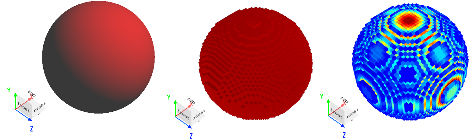
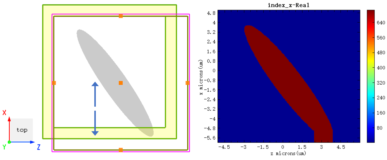
- Use the Index monitor to check the created structure. Please refer to Index monitor;
- Use the shortcut tool View the current mesh data to view the current mesh data.
Boundary #
When Extend structure through PML is selected on the boundary condition setting interface in the solver and the structure extends beyond the simulation area, the device extends along the axis if using the PML boundary.
More #
Current View Surface and Structure #
The undersurfaces of the structure vary with the selected viewing plane types. In 3D view, select the plane observed through Switch to top (ZX) view as the undersurface of the structure.
In this setting, the component plane can be added in the toolbar of the composite viewer, or through script selection:
(In 3D view, select Switch to top (ZX) view)
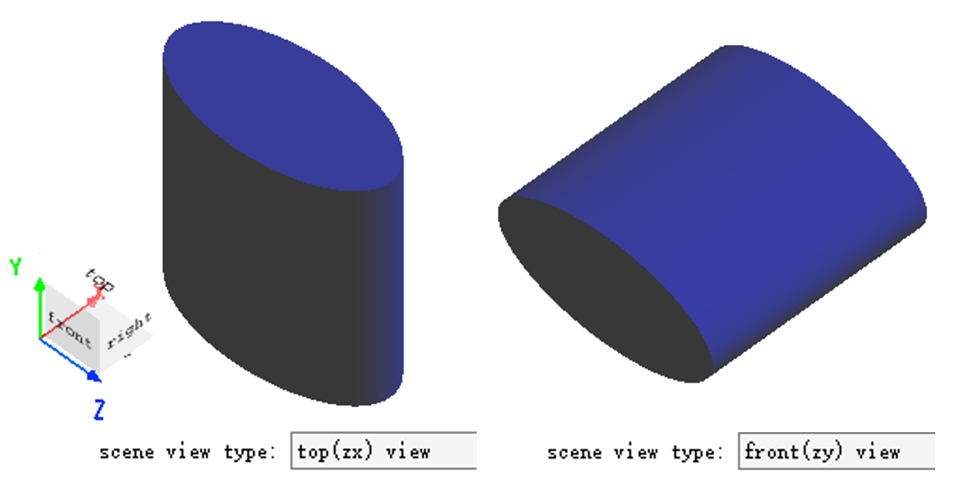
Scene view type is view-only. No modification is allowed. Please use the Rotation tab to change the "Direction" of the built structure.