Import and Export
Structure Import and Export #
Import #
Structure can be imported into the software in two ways: interface import and script import.
The software supports importing files in specified formats into a particular project. In the Home tab of the software's Ribbon, click Import to select the file type to be imported.
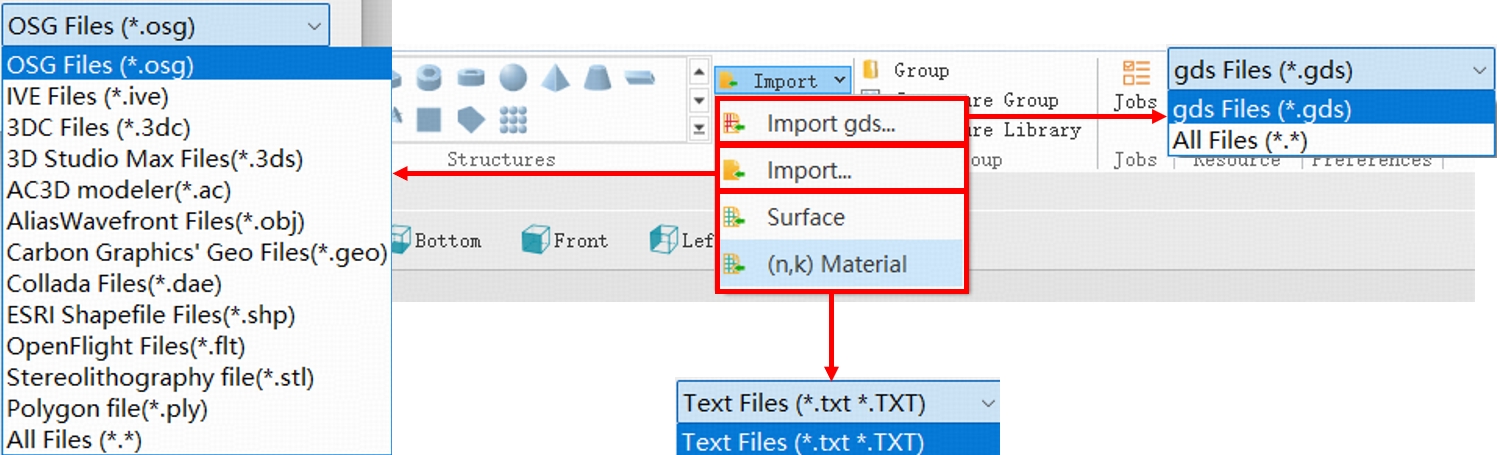
The details of file types in the figure can be found in the following table:
| Number | Name | Description |
|---|---|---|
| 1 | Gds | Gds is a binary file format originally developed by Calma and now maintained by Cadence, commonly used to store information such as geometric shapes and hierarchical structures of semiconductors. |
| 2 | Osg | Osg file is a 3D scene graph developed by the open 3D engine OpenSceneGraph (OSG), which can store various model information. |
| 3 | Ive | Ive file is a binary scene format defined by OSG, typically used to save 3D models. |
| 4 | 3dc | 3dc file is a file format for storing 3D media created by the 3DCrafter from Amabilis. |
| 5 | 3ds | 3ds is a 3D graphics file format developed by Autodesk, widely used in 3D modeling and animation. |
| 6 | Ac | Ac file is a type of 3D model file created by the AC3D software. |
| 7 | Obj | The Obj format, originally developed by Wavefront, has become a widely used format for 3D models. |
| 8 | Geo | Geo file is a 3D model format often associated with certain 3D software (such as Carbon Graphics). |
| 9 | Dae | Dae is a file format launched by Collada for storing and transferring 3D models between different software. |
| 10 | Shp | Shp file is an open format for spatial data developed by Environmental Systems Research Institute(ESRI). |
| 11 | Flt | OpenFlight (Flt) was originally developed by Software Systems Inc. for the MultiGen software, and is now maintained by Presagis, primarily used in real-time visual simulation and other fields. |
| 12 | Stl | Stl is developed by 3D Systems and uses unstructured triangles to describe 3D objects. |
| 13 | Ply | Ply is a 3D data format developed by Stanford University for polygonal models. |
| 14 | TXT | TXT is a plain text file containing unformatted text. |
Export #
Structure in the software can be exported in two ways: interface export and script export.
The software supports exporting files in specified formats. In the Home tab of the software's Ribbon, click Export to select the file type to be exported.
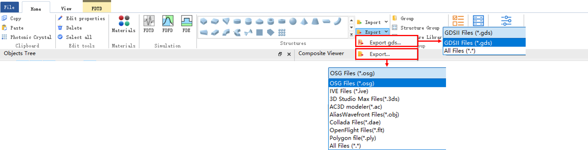
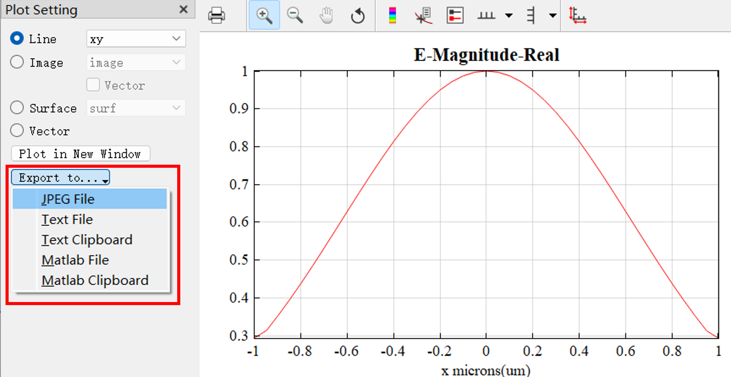
Click the Export to... in the Data Visualizer window. You can export data to files of specified types.
Taking the export of GDS files as an example, users can refer to the following steps:
GDS files are widely used in layout design and tape-out in micro-nano fabrication, optoelectronics, and semiconductor fields. Note that GDS files can generally only export 2D structures. For some complex structures, there may be a loss of precision, so it is recommended to verify after export.
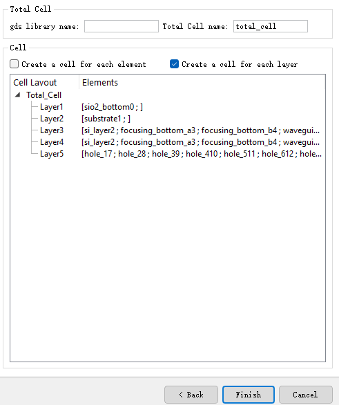
- In the Home tab of the main menu, find the Export button, click it, and select the Export gds option.

- In the pop-up export dialog, set export options such as specifying GDS layers and other parameters.
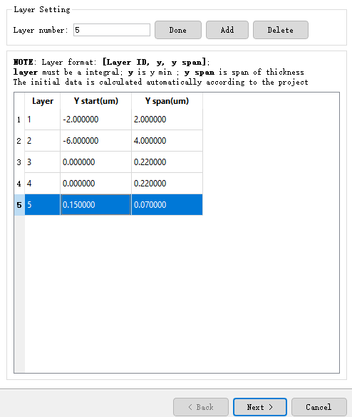
- Click the Next button to proceed with export settings, usually keeping the default settings.
-
Click the Finish button, select the save directory for the GDS file, and complete the export.
-
After exporting, you can use third-party GDS viewing tools to open and check the exported GDS file.
Notes:
- If the structure contains custom layers or special graphics, it is recommended to set layer mapping and thickness in the export dialog to ensure accurate layer information in the GDS file.
- If errors occur or the file is incomplete during export, please check whether the structure design is standard, or try simplifying the structure and exporting again.
- GDS files only support 2D structures. In software, the default plane is ZX. If you need to export 3D structures, please choose other supported file formats.
Surface Import #
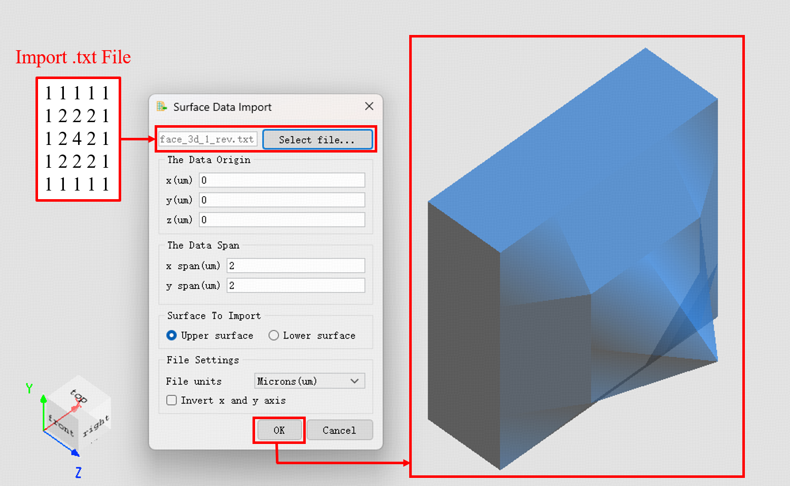
The software supports direct import of .txt format data files and converts them into software-compatible surface models. Users can quickly import 3D design data of complex optical components (such as freeform lenses or grating structures) without manual modeling, significantly improving workflow efficiency.
The meanings of the options in the above figure are as follows:
| Name | Description |
|---|---|
| Select File | Select the .txt file to import. Please note that the file format must meet specific requirements. |
| The Data Origin | X/Y: Determines the origin of the imported structure's data based on the format of the imported file. If the file defines the plane coordinate position, it will be used as the offset reference. If not defined, the offset will be relative to the center of the current Composite Viewer . Z: Sets the display thickness of the imported structure. For example, if the imported plane has an actual thickness of 2 μm, this value should be set greater than 2 μm to ensure the complete display of the structure. If the set value is smaller than the actual thickness, the excess part will not be displayed. |
| The Data Span | x/y span : Sets the width in the X/Y directions. If the file contains coordinate information, the software will automatically set this value. If not, the structure will be scaled according to this setting. |
| Surface to Import | Selects the surface corresponding to the imported data. Options: Upper Surface or Lower Surface. |
| File Settings | File units : Sets the unit of the imported data. Invert x and y axis : If the coordinate axes are flipped during file export, check this option to automatically correct it. |
Two formats of .txt files are supported for import:
- Complete coordinate format: Contains the number of data points, coordinate values, and corresponding Z(X,Y) data in the X/Y directions.
- Height data-only format: Contains only Z(X,Y) numerical values.
For more details, please refer to Importing a Freeform Surface.
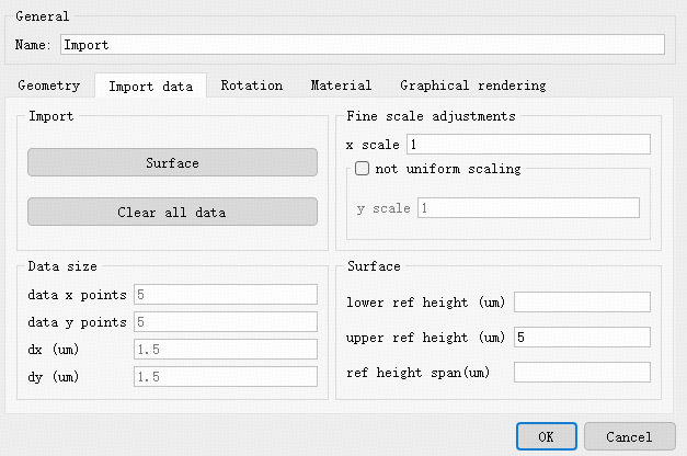
After successfully importing a structure, the software will generate a corresponding Import structure in the object tree. Compared to ordinary structures, this node additionally contains an Import data editing page. The meanings of its parameters are shown below:
| Category | Name | Description |
|---|---|---|
| Import | Surface | Click to open the import window (same as above) to import another surface for the current structure, creating a double-sided structure. |
| Clear all data | Clears all surfaces of the current structure. | |
| Data size | Data x/y points | Displays the original number of data points in the X and Y directions, respectively. |
| dx / dy | Displays the equidistant discrete interval between data points in the X and Y directions, respectively. Only displayed when the data is equidistantly discrete. | |
| Fine scale adjustments | x scale | Sets the scaling ratio in the X direction. When non-uniform scaling is not enabled, this scaling is proportional. |
| y scale | Enabled after checking not uniform scaling , used to independently set the scaling ratio in the Y direction. | |
| Lower ref height | Defines or displays the thickness of the lower surface of the structure. | |
| Surface | Upper ref height | Defines or displays the thickness of the upper surface of the structure. |
| Ref height span | Defines or displays the overall thickness of the structure. |
Import (n,k) Materials #
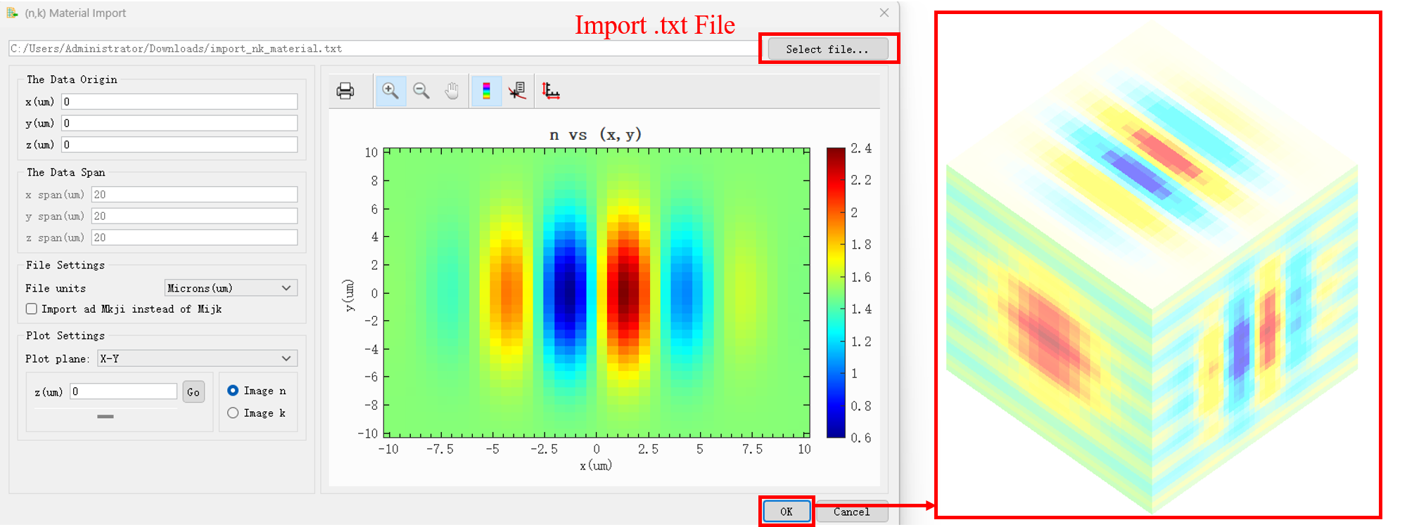
The software supports importing .txt files to create structures with spatially varying refractive indices. The imported data contains complex refractive index information for a specified single frequency.
The meanings of the options in the figure above are as follows:
| Name | Description |
|---|---|
| Select File | Select the .txt file to import. Please note that the file format must meet specific requirements. |
| The Data Origin | X/Y/Z: Sets the position of the imported structure's data origin within the global coordinate system. |
| The Data Span | x/y/z span: Displays the width of the imported data along the X, Y, and Z axes. This information is read-only and cannot be modified. |
| File Settings | File units: Sets the unit of measurement for the imported data. Import Mkji instead of Mijk: If the storage order of the data file is incorrect, check this option to reverse the data reading order. |
| Plot Settings | Plot plane: Select the cross-section for visualization. Image n / Image k: Choose to plot the real part (n) or the imaginary part (k) of the refractive index. |
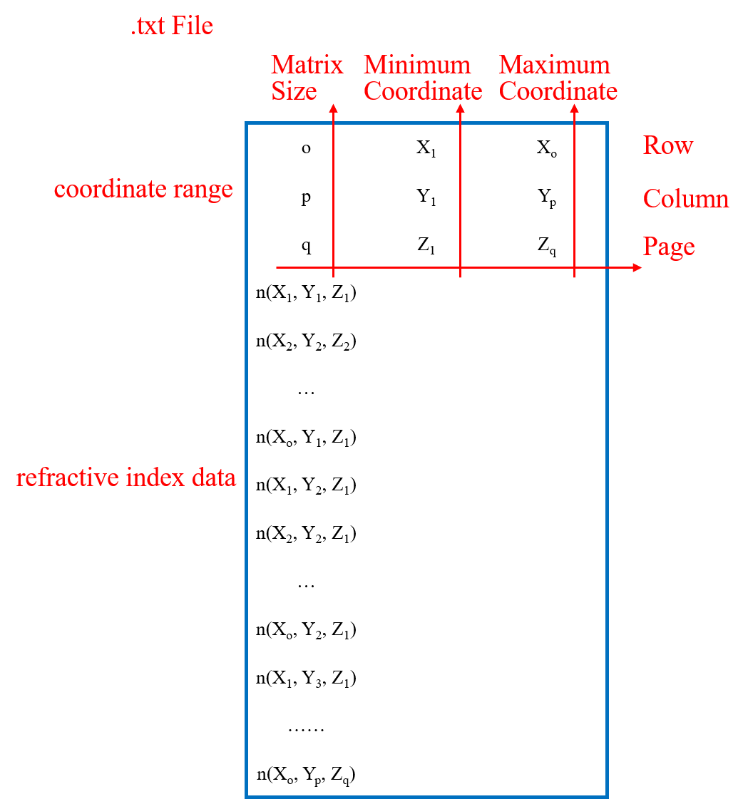
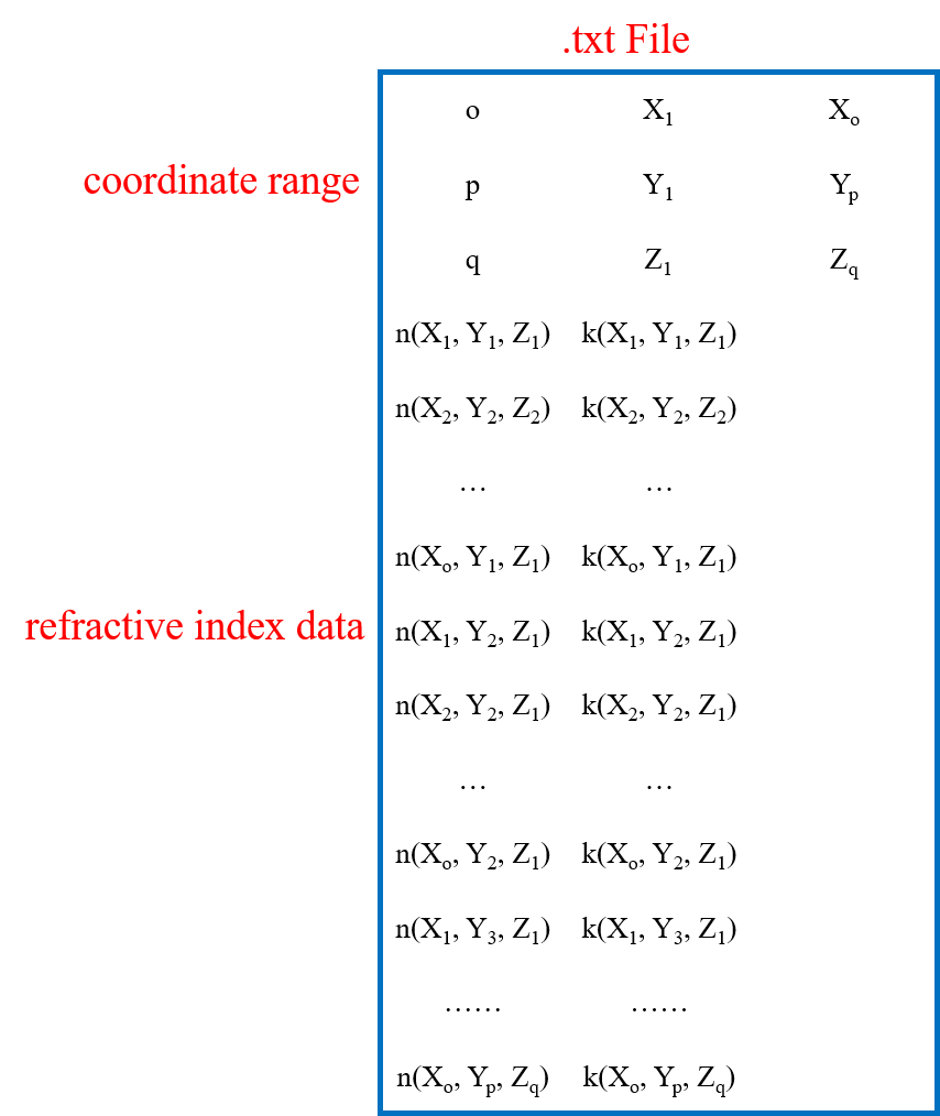
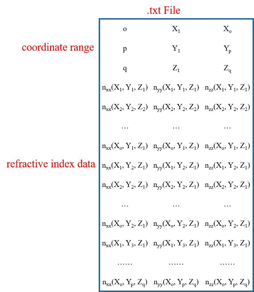
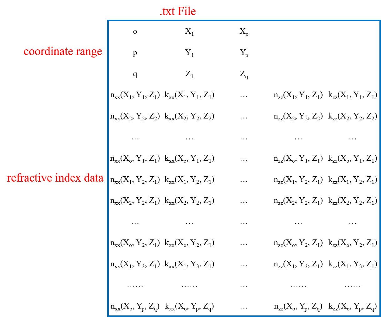
To distinguish between isotropic and anisotropic materials, there are four file arrangement formats. Their basic structure is consistent: the first three rows define the number of data points, the minimum coordinate, and the maximum coordinate for the X, Y, and Z directions, respectively. Subsequent rows contain the refractive index matrix data arranged in a specific order.
- Isotropic Materials
- Refractive index with real part only (n):
- Complex refractive index (real part n and imaginary part k):
- Anisotropic Materials (nxx,nyy,nzz)
- Refractive index with real part only (n):
- Complex refractive index (real part n and imaginary part k):
When importing, ensure that the coordinate points of the refractive index data are uniformly spaced along the X, Y, and Z axes. After successful import:
- The software will create a corresponding Import structure in the object tree.
- During solving, this structure uses its own internally defined uniform grid.
Additionally, the property page of this structure will include an extra Import Data tab for viewing and adjusting the structural parameters. The details are as follows:
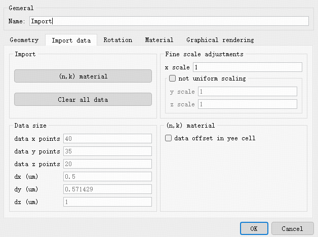
| Name | Description | |
|---|---|---|
| Import | (n,k) material | Click to open the import window, allowing you to re-import the material data file. |
| Clear all data | Clears the data of the current structure. | |
| Data size | Data x/y/z points | Displays the original number of data points in the X, Y, and Z directions, respectively. |
| dx/dy/dz | Displays the equidistant discrete interval between data points in the X, Y, and Z directions, respectively. | |
| Fine scale adjustments | x scale | Sets the scaling ratio in the X direction. When non-uniform scaling is not enabled, scaling is proportional across all directions. |
| y/z scale | Enabled after checking not uniform scaling , used to independently set the scaling ratio in the Y or Z direction. |