

Groups
Groups #
In the software, a Group is a container for organizing and managing simulation objects. According to their purpose and functionality, groups can be divided into three types: Regular Group, Structure Group, and Assembly Group. User can choose the appropriate group type based on your actual needs.
Regular Group #
The Regular Group is the most basic group type, serving as a simple container for logically organizing multiple objects (such as geometries, monitors, light sources, etc.) together. The main uses of the Regular Group are:
- Grouping related objects in the object tree to make the model structure clearer.
- Supporting unified movement, rotation, hiding, or deletion of all objects within the group.
- Can contain most types of objects, but cannot contain other group types such as Assembly Group.
The Regular Group does not provide special performance optimization or batch instantiation capabilities, and is suitable for managing a small number of non‑repetitive objects. You can create a Regular Group through the graphical interface or the script command addgroup.
Structure Group #
This section describes structure groups.
Structure group is a collection of structures and serves as a tool for managing and editing objects within the group, which facilitates users to model and design optical devices.
Features:
- Not only enable unified operations on structure units within a structure group, but also allow users to change properties of individual objects within a group.
- The setup script allows users to customize any structure group to facilitate overall optimizations and sweeps.
Utilizing structure groups for modeling makes the design of optical devices easy and efficient.
Built-in Structure Group Library #
For common structures, the software offers a variety of structure groups to facilitate users in accomplishing complicated modeling tasks.
Built-in Structure Group Library #
| Name | Description |
|---|---|
| Cylinders | Including Custom revolution, Gear cylinder, Rough cylinder, Rough wire, and Rounded cylinder. |
| Cylindrical fibers | Including Bragg fiber, Core-cladding fiber, and Vertical multilayers. |
| Ellipsoids | Including Coated ellipse, Coated sphere, Dimer sphere, and Hemisphere. |
| Extruded polygons | Including All rounded quadrilateral, Complex n-sided polygon, Cross, Equation mirrored line, General polygon, Isosceles trapezoid, N-sided equilateral polygon with rounded corners, N-sided equilateral polygon, Parallelogram, Rectangular polygon with rounded corners, Star polygon, Equilateral triangle, Isosceles triangle, and Right-angle triangle. |
| Gratings | Including Blaze grating, Bragg grating, and Grating coupler. |
| Integrated optics | Including 180-deg waveguide bend, 90-deg waveguide bend, Cross waveguide, Directional coupler, Ring resonator, S-bend waveguide, Straight waveguide, Y-combiner, and Y-splitter. |
| Photonic crystals | Including BCC PC lattice, Circular lattice PC array, FCC PC lattice, FCC(111) PC array, Hexagonal lattice PC H-cavity, Hexagonal lattice PC L-cavity, Hexagonal lattice PC array, Hexagonal lattice PC intersection, Hexagonal lattice PC waveguide, Rectangular PC lattice, Rectangular lattice PC array, Rectangular lattice PC waveguide, Woodpile, and Rectangular lattice PC intersection. |
| Polyhedrons | Including Disdyakis dodecahedron, Regular octahedron, and Truncated octahedron. |
| Pyramids and cones | Including Coated pyramid, Cone, Diamond, N-sided Pyramid, N-sided Truncated pyramid, Parabola cone, Rounded tip cone, Tetrahedron, Truncated cone, and Truncated ellipse cone. |
| Random particles | Including Gaussian random particle distribution, Linear random particle distribution, and Uniform random particle distribution. |
| Toroids | Including Circular toroid, Ellipse toroid, Equilateral n-side polygon toroid, and Partial circular toroid. |
| Uncategorized structures | Including Helix and Spiral. |
Add and Change #
Add Built-in Structure Group #
You can open the built-in structure groups available in the software, and view the options shown as below:
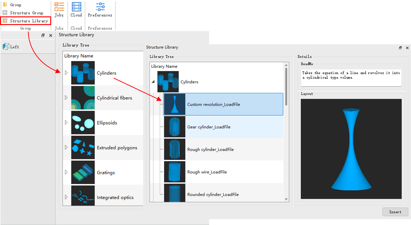
Edit Built-in Structure Group #
Add a structure group in the Cylinders>Gear Cylinder, and open the Edit properties.
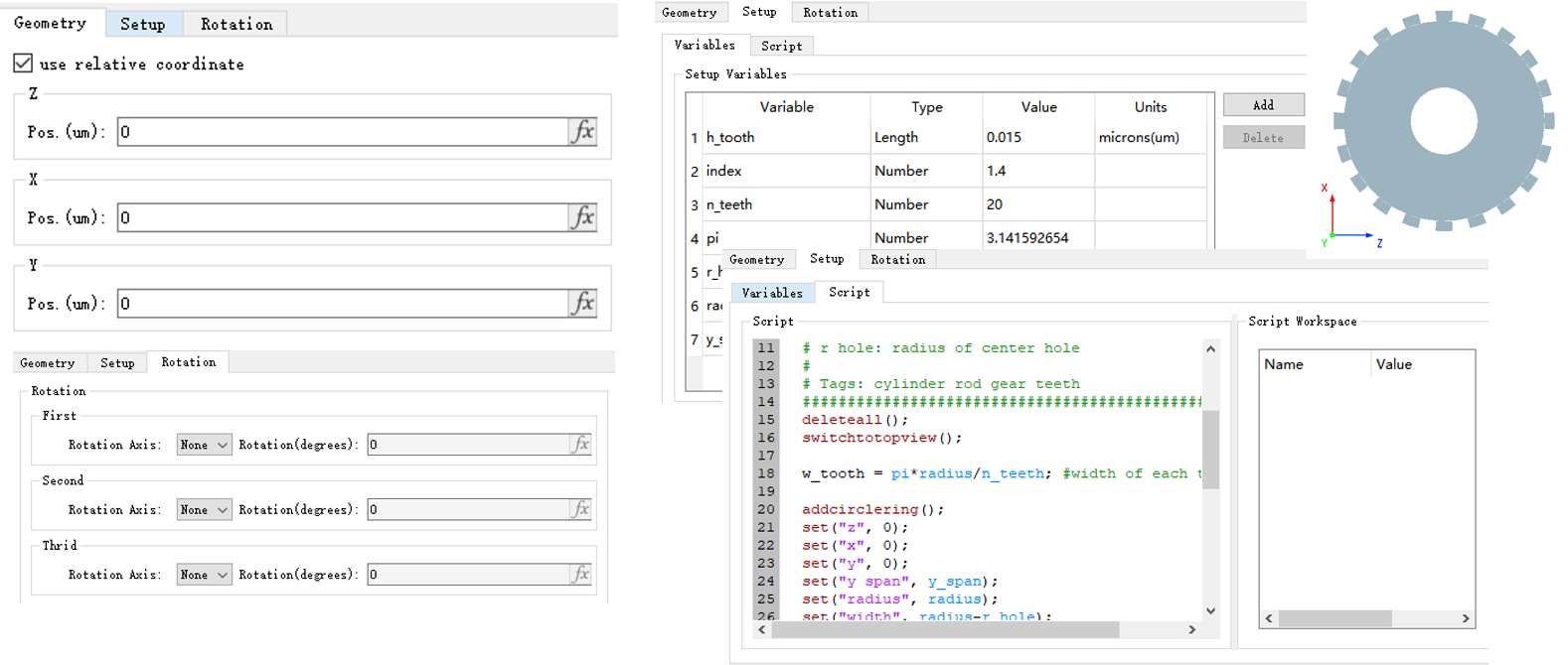
The built-in structure group in the software not only enables modification of global parameters (relative position, rotation) or script variables, etc., but also allows users to change parameters of an individual unit within the structure group, or to delete/add a certain structure unit.
Custom Structure Group #
Create #
The software supports custom structure groups that can be created according to the following general procedures:

Example: Circular Aperture Diaphragm #
Based on these procedures, you can create a structure group for a common aperture.
- Analyze the composition of the components and divide the complex structure into a combination of multiple basic units. For example, the aperture is usually a circular shape on a flat plate. Users can choose the 2D polygon structure to establish the aperture.
- Add an empty structure group according to the operations shown in the figure:

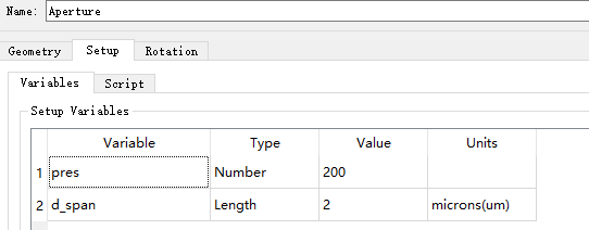
- Define the aperture parameters:
-
Write the script on the structure group Script page, including the code as follows:
deleteall; # setup variables Rin = 0.5e-6; Lout = 2e-6; res = 100; # setup script xin = Rin.*cos(linspace(0,2*pi,res)); yin = Rin.*sin(linspace(0,2*pi,res)); xout = [Lout,Lout,-Lout,-Lout,Lout,Lout,Rin]; yout = [0,Lout,Lout,-Lout,-Lout,0,0]; V = [xout,xin; yout, yin]; add2dpolygon; set("name","2d ring"); set("vertices",V); -
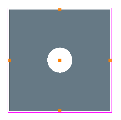
The structure group created is shown in the figure below (the image has been processed):
Assembly Group #
The Assembly Group is a special group type designed for efficiently creating complex structures composed of a large number of repeated or similar objects, such as metalens arrays. Its core philosophy is "define once, reuse repeatedly" – by using a prototype object and a parameter mapping table, multiple instances can be generated in batch, significantly accelerating geometry construction and meshing.
An Assembly Group consists of the following elements:
- Prototype: The sole child object within the group, which can be a basic geometric shape (e.g., box, cylinder) or a Structure Group. All instances are generated based on this prototype. The prototype cannot be another Assembly Group and must not contain spatially varying materials.
- Parameter List: A cell array that lists the names of the prototype parameters that need to vary, e.g.,
{"x", "y", "radius"}. - Mapping Table: A matrix that provides the specific parameter values for each instance. The number of rows equals the number of parameters, and the number of columns equals the total number of instances. Each column corresponds sequentially to the values for the parameters in the parameter list.
The parameter list and mapping table are defined via script and assigned to the Assembly Group using setnamed. The following code snippet illustrates the syntax for defining these parameters. For a complete working example, please refer to the Example section on this page.
# For demonstration purposes only
# Define parameter list and mapping table
params = {"x", "y", "radius"};
mapping = [x_1,x_2;
           y_1,y_2;
           R_1,R_2];
# Assign the parameter list and mapping table to the assembly group
setnamed("assembly_group", "parameters", params);
setnamed("assembly_group", "mapping", mapping);
Key features of the Assembly Group include:
- Prototype + Mapping: The group contains only one prototype (a basic geometry or Structure Group) and uses the mapping table to assign different parameter values to each instance.
- Variation Management: Rotations and translations are treated as free variables and do not consume variation slots.
- Script‑Driven: Creation and configuration of Assembly Groups rely mainly on script commands (such as
addassemblygroup,addtogroup,setnamed, etc.), eliminating the need for complex GUI interactions.
Example #
This example demonstrates how to quickly create an array of 4 cylinders, each with a different position and radius, using an Assembly Group.
deleteall;
switchtorightview;

# Create and name the assembly group
addassemblygroup;
set('name', 'assembly_grp');

# Create the cylinder prototype
addcircle;
set('radius', 0.5e-6);
set('z span', 2e-6);
set('x', 0);
set('y', 0);

# Add the prototype to the assembly group
addtogroup('assembly_grp');

# Define the parameter list: X shift, Y shift, radius
setnamed('assembly_grp', 'parameters', ['x pos', 'y pos', 'radius']);

# Define the mapping table
mapping = [0, -2, 2, 0;      # x coordinates of each instance (um): 0, -2, 2, 0
           0, 3.5, 3.5, 5;   # y coordinates of each instance (um): 0, 3.5, 3.5, 5
           4, 1, 1, 2] * 1e-6;    # radius of each instance (um): 4, 1, 1, 2

setnamed('assembly_grp', 'mapping', mapping);