

Setting RCWA Simulation Control Panel
RCWA Simulation Control Panel #
This section introduces the simulation control panel for the Rigorous Coupled‑Wave Analysis (RCWA) solver.
The RCWA solver is a semi‑analytical simulation tool based on rigorous coupled‑wave analysis. It is used to efficiently and accurately analyze the optical response of multi‑layer structures with in-plane periodic patterns (such as diffraction gratings, metasurfaces, and photonic crystals) under plane‑wave incidence, including reflectance, transmittance, diffraction efficiency, and internal field distributions.
The functions of each button on the control panel are shown in the figure below:

| Name | Description | |
|---|---|---|
| Design | To Design | Switch back to the Design view to access tools for structure creation and solver settings, etc. |
| Graphics | Translucent | Set the transparency of the structure; 1 means opaque, 0 means fully transparent. |
| Hide Materials | Hide the material structure in the view; enabled when checked. | |
| Hide Fields | Hide the field distribution in the view; enabled when checked. | |
| Progress | Status | Display the current simulation status and progress. |
| Tool | Control the opening and clearing of simulation data files. |
RCWA Ribbon #
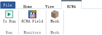
The RCWA ribbon provides simulation run control and component addition functions. The functions of each button are shown in the figure below:
| Name | Description | |
|---|---|---|
| Run | To Run | Run the RCWA simulation and automatically switch to the simulation control panel. |
| Monitors | RCWA Field | Add an RCWA Field component to record the spatial distribution of the electromagnetic field within the simulation region. |
| Mesh | Mesh | Add a custom mesh to apply finer mesh refinement to specific regions. |
RCWA Field #
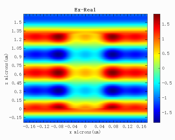
RCWA Field records the spatial distribution of the electromagnetic field within the simulation region. After the simulation completes, the internal field distribution of the multilayer structure can be viewed through this component, facilitating analysis of how the optical field propagates and localizes within the structure.
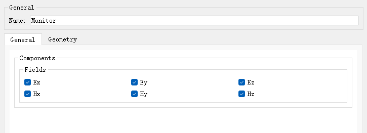
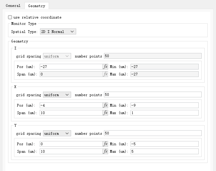
After clicking the RCWA Field button to add the component, configure the settings in the pop-up Edit properties window, which contains the General and Geometry tabs.
- The General tab is used to set the field components to be recorded.
- The Geometry tab is used to set the position and extent of the recording region, as well as the number of mesh points in each direction.
The figure below shows the field distribution above a nanorod structure under plane-wave incidence:
Mesh #
The Mesh button is used to add a custom mesh within the RCWA simulation region, applying finer mesh refinement to specific regions. For detailed settings of the custom mesh, please refer to Custom Mesh Settings.