Optical Material
Optical Material #
This section describes optical materials.
Optical materials in the software are supported in all algorithms (FDTD, FDFD, and FDE).
The software provides a wide variety of pre-defined material data and models (e.g., dielectric, conductive, model, sampled-data, nonlinear, and emerging hot materials) and allows users to add custom ones. In the material library, users can add new materials, edit their parameters, perform manual model fitting, and check the fitting effectiveness.
Users can add and edit materials by using scripts. See Script.
Optoelectronic Materials #
Definition: Complex Refractive Index N #
In general, we introduce the imaginary part κ of the refractive index, and use the complex refractive index N to define the material:
N=n+iκ
Where, n is the real part of N, indicating the refractive index in the usual sense; κ is the imaginary part of N, indicating the attenuation (κ>0) or gain (κ<0).
Complex Refractive Index and Complex Permittivity #
The relationship between the complex permittivity ε=ε1+iε2 and the complex refractive index N is:
ε1ε2=n2−κ2=2nκ
Material Tag #
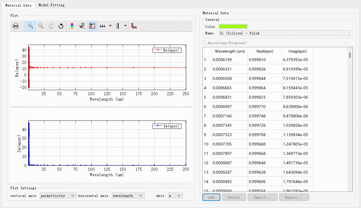
The colors and names of the materials in the material library can be set in the Material data tab.
| Name | Default | Description |
|---|---|---|
| Color |  |
Specifies the color of the material. |
| Name | Untitled material | Sets the name of the material. It is a string type. |
Frequency-Domain Characteristics: Dispersion Relation #
Dispersion Relation #
According to the relevance between the refractive index of a material and frequency (or wavelength), materials can be divided into:
- Non-dispersive material: The refractive index of a material in a certain band is a constant;
- Dispersive material: The refractive index of a material is a function of frequency (or wavelength). When adding dispersive materials, it is necessary to specify the frequency (or wavelength) range corresponding to the refractive index.
Material Fitting #
By the fitting algorithm, the material is used as a model in the project simulation.
Below is the Model fitting window.

This window displays tabs such as the material bandwidth range, fitting parameter settings, and fitting status. The RMS error is used to evaluate the effect of material fitting. For more details, please refer to the Material Fitting section below.
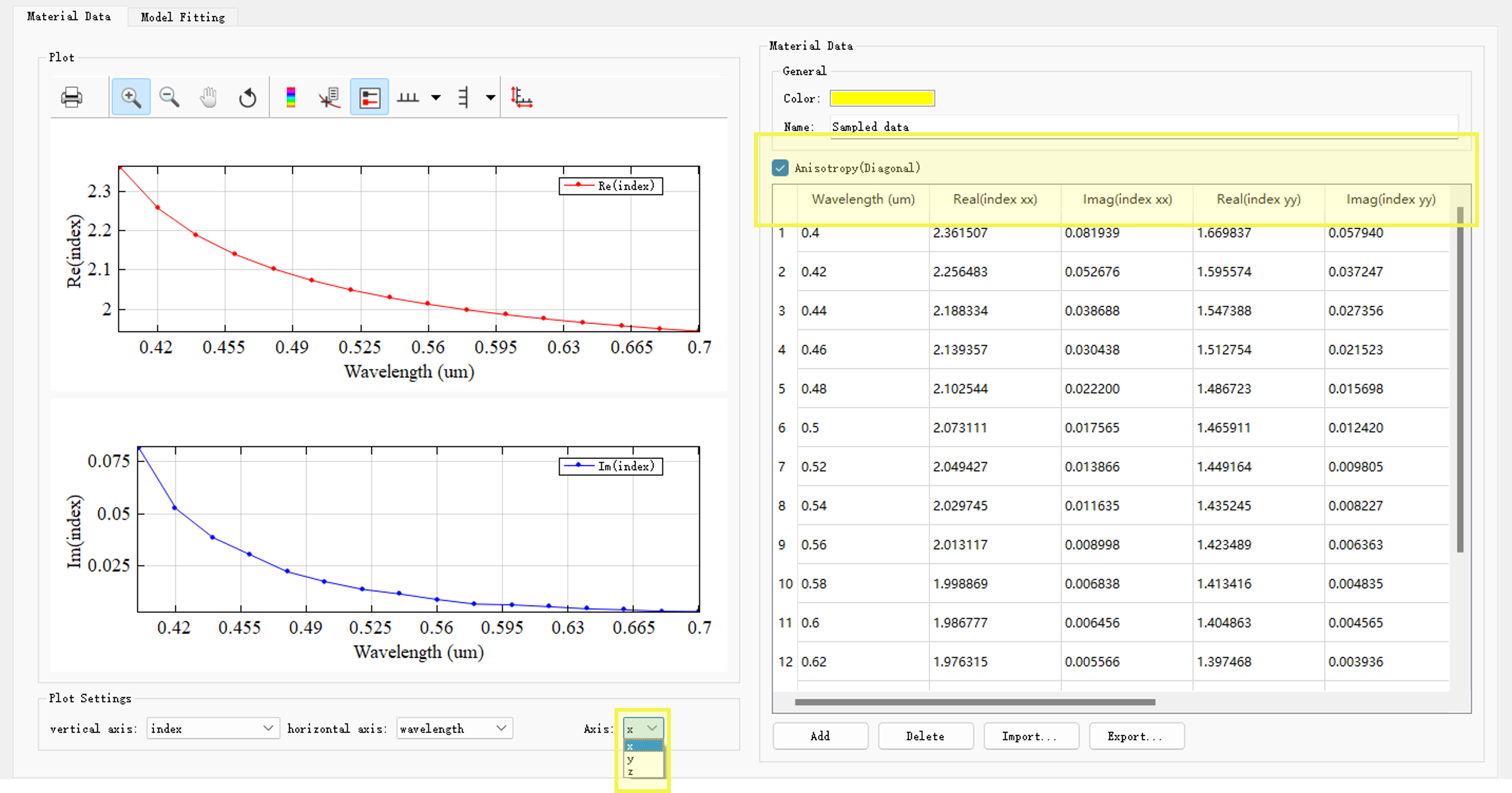
Spatial Characteristics: Isotropic and Anisotropic #
The software supports the creation of isotropic materials and diagonal anisotropic materials.
The mathematical expression for the dielectric constant of a diagonal anisotropic material is:
ε=⎣⎢⎡εxx000εyy000εzz⎦⎥⎤
On the Material data page, select Anisotropy (Diagonal), and set εxx,εyy,εzz respectively. This button is applicable to all material models (PEC is not supported). In the Plot window, switch the Axis of Plot settings to view material data in different directions.
General anisotropic materials are not currently supported, namely:
ε=⎣⎢⎡εxxεyxεzxεxyεyyεzyεxzεyzεzz⎦⎥⎤
Nonlinear Response #
In general, any material features nonlinear response; therefore, the nonlinear response is not a separate material feature. For ease of description, this section does not distinguish between nonlinear material and nonlinear response.
In software, a nonlinear material consists of a basic material and a nonlinear coefficient.
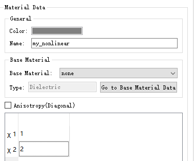
The software supports two types of nonlinear materials: Chi2 nonlinear and Chi3 Raman/Kerr nonlinear.
For more detailed settings, please refer to Nonlinear.
Material and Material Library #
Material Model #
Currently, the software supports the following material models:
| Name | Description |
|---|---|
| Dielectric | Refers to a material with a constant refractive index, which is independent of wavelength. See Dielectric. |
| (n, k) Material | NK material refractive index N=n+iκ, and nk material refers to the material at a single frequency point (or center frequency point). See (n, k) Material. |
| Conductive | Refers to a model describing a conductive material. The conductive material is frequency-dependent. See Conductive. |
| Conductive 2D | Refers to a model describing 2D conductive material. See Conductive. |
| Debye | Refers to individual particles that do not interact with each other (such as gases). The Debye model is frequency-dependent. See Debye. |
| Lorentz | Refers to a model describing a semiconductor material. The Lorentz model is frequency-dependent. See Lorentz. |
| Drude | Refers to a model describing plasma/metal materials. The Drude model is frequency-dependent. See Drude. |
| PEC | Describes a perfect conductor. See PEC. |
| Sampled data | Using the experimental data of the material. It can be fitted to a stable model of the material in the specified frequency band. See Sampled data. |
| Sampled 2D data | Using real experimental data of the 2D material. It can be fitted to a stable model of the material in the specified frequency band. See Sampled data. |
| Chi2 nonlinear; Chi3 Raman/Kerr nonlinear | Describes the nonlinear response of optical materials. See Nonlinear. |
| Graphene | Describes emerging materials, that is, surface conductive graphene model in the specified frequency band. See Graphene. |
| RLC | Describes lumped elements integrating with resistance (R), inductance (L), and capacitance (C). |
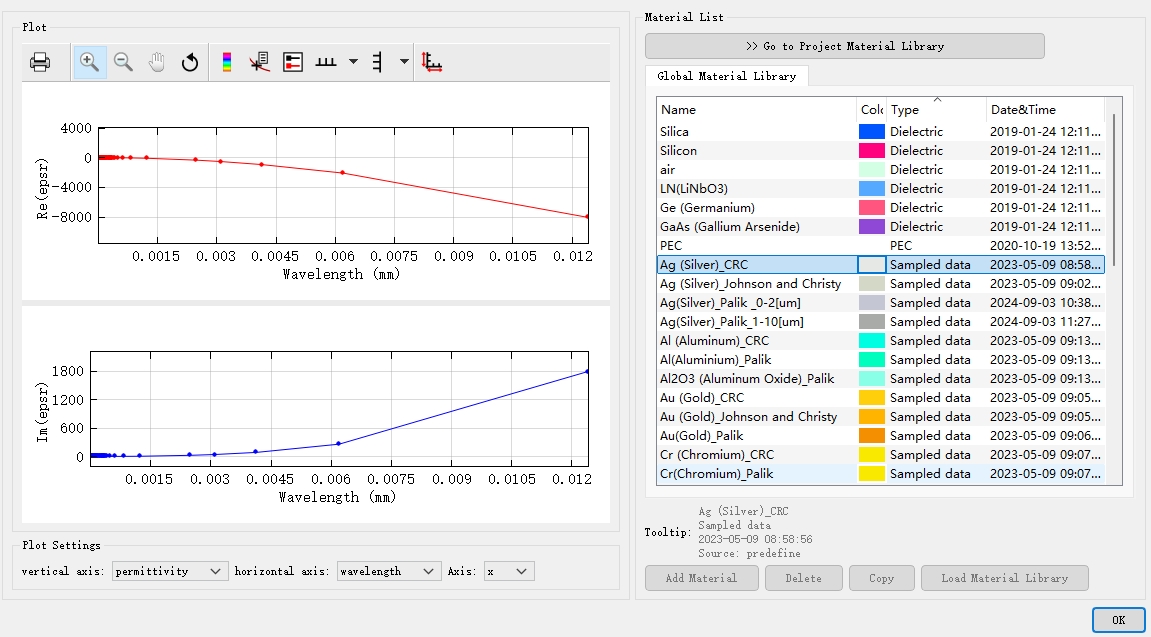
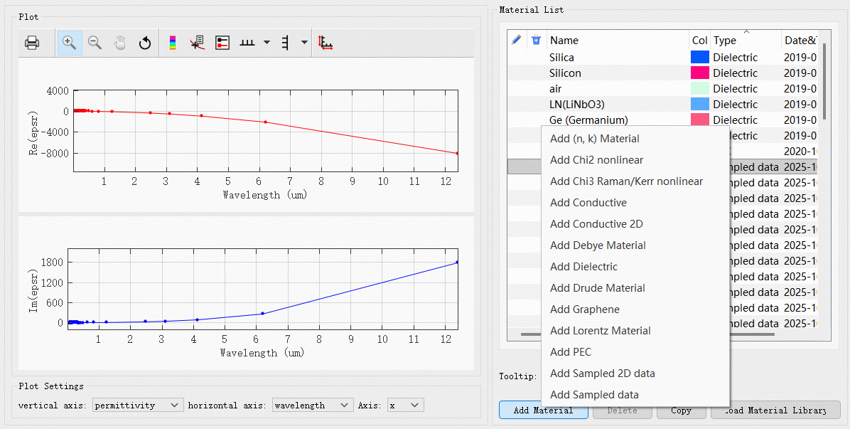
Material Library #
The library storing materials is the material library.
The software features both an Optical Material Library and an Electrical Material Library. The former can be used with the FDTD, FDFD, and FDE solvers, while the latter is exclusively supported by the FDCharge solver. In addition to the properties found in optical materials, electrical materials include specific electrical characteristics. For more details, please refer to the Finite-Difference Charge Carrier Transport (FDCharge) Solver section. This section covers only the Optical Material Library.
When building a structure, users can select materials from the Optical Material Library in the material tab of the structure. Furthermore, based on actual material properties, users can add new materials to the Optical Material Library by choosing an appropriate material type. Different material types require different parameter sets. For specifics, please see the material types table above.
Material Fitting #
The software fits the experimental data of the material into a stable material model through the fitting algorithm.
Parameter Settings for Material Fitting #
The Material fitting window has the following settings:
| Name | Default | Description |
|---|---|---|
| Bandwidth Settings | Wavelength setting range | Bandwidth settings include the frequency/wavelength range of the material. By default, the bandwidth range displayed on this tab is consistent with the source. |
| Tolerance type | RMSE | RMSE (Root mean squared error) and RRSE (Root relative squared error) are the most significant parameters for characterizing fitting error. Definition methods are slightly different: RRSE=[i=1∑n(pi−ai)2]/[i=1∑n(aˉ−ai)2], RMSE=i=1∑n(pi−ai)2/n. |
| Tolerance | RMSE: 0.1 | Maximum allowable tolerance for material fitting. |
| Max coefficients | 6 | The allowed highest order in material fitting models (polynomials). |
| Improve FDTD stability | Selected | Improves the stability of the fitted model. |
| Imaginary weight | 1 | Imaginary weight for material fitting. |
| Ratio | 20 | One of the custom parameters of the PSO. By default, ratio does not need to be changed. |
| Max generations | 240 | The maximum number of iterations that need to be run, by default, does not need to be changed. |
| Generation size | 500 | The number of particles in each iteration, by default, does not need to be changed. |
Auto-Fitting #
The software provides the automatic material fitting methods for the fitting of material data.
flowchart TD
Choose_SampledMaterial[Choose material] --User define--> MaterialFitting[Material fitting program];

Lambda/Frequency-.Base on source.-> MaterialFitting[Material fitting program];
parameters[RMSE, Max coefficients]-.Default.-> MaterialFitting[Material fitting program];
Auto-fitting, that is:
- Parameters required for the fitting program. The fitting parameters are default values. Users only need to specify the material;
- The fitting program runs automatically prior to simulation.
Evaluation of the Fitted Model #
The software provides parameters and images of the fitting results for the evaluation of the material fitting model.
flowchart TD
MaterialFitting[Material fitting program] -->Fitting_status[Fitting status];
MaterialFitting[Material fitting program] -->Figure;

Fitting_status --> parameters2[RMSE/RRSE, Max coefficients];
Fitting_status -->Lambda/Frequency;
Fitting_status -->Others[...];
Evaluation of the fitted model:
- The fitting effect of the fitted model is evaluated according to the returned RMSE/RRSE and images;
- If the fitted model does not meet the simulation requirements, the fitting parameters should be modified.
Custom Fitting #
The software allows the modification of each parameter, including those in the advanced settings, to meet the fine-tuning requirements of the fitted model. However, this function is very complex, and is only recommended for advanced users, that is, those users who are in good command of the software material fitting settings. Otherwise, it may be counterproductive.
flowchart TD
Choose_SampledMaterial[Choose material] --User define--> MaterialFitting[Material fitting program];

Lambda/Frequency-.Base on source.-> MaterialFitting[Material fitting program];
parameters[RMSE, Max coefficients]-.Default.-> MaterialFitting[Material fitting program];
Custom fitting means that
- The definition method and input value of the parameters required by the fitting program can be defined by users;
- The process may require multiple attempts until the fitted model meets the simulation needs;
- The wavelength on the custom fitting interface is for model display only, and cannot be used for FDTD computation.
Material and Simulation #
Creating Material Model #
Before starting the simulation, confirm the type of material required. If the material exists in the Optical Material Library, it can be added directly in the structure editing interface.
For other material types, you need to click Add material in the Optical Material Library window to create the required model material.
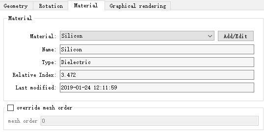
Material Assignment Structure #
Right-click the structure, enter the Edit properties, and switch to the Material page. Click Add/Edit to enter the Project material library, and select the target material. Complete the process of assigning the material to the structure.
Checking Material Model #
Different numerical solvers have their own complex set of solutions for the discretization of the structure and the assignment of material data. Checking materials is an important part of simulation inspection.
The software provides a variety of ways to inspect materials in different phases of modeling and simulation.
-
Optical Material Library
In the Optical Material Library, use the Material Fitting tab to evaluate material models based on graphics or data. For details, please refer to the Material Fitting section above.
-
View the current mesh data
After the material is added to the structure, click View the current mesh data on the left toolbar of the software to visually view the distribution of the drawing material on the three-dimensional spatial mesh.
-
Index monitor
Index monitor allows users to accurately obtain graphics (and data) of material distribution at specified spatial locations, making it easy to check the correctness of material creation.
Case: Negative Refractive Index Material #
Negative refractive index material is an artificial optical structure, and the refractive index is negative in a certain frequency range. See Negative refractive index materials.