Phase-Shifted Bragg Grating
Preface
A Bragg grating (BG) is an optical device formed by introducing a periodic refractive index modulation in a waveguide or optical fiber. It selectively reflects a specific wavelength that satisfies the Bragg condition while transmitting the rest. A phase-shifted Bragg grating (PSBG) is based on a conventional Bragg grating, but introduces one or more abrupt refractive index changes (i.e., phase shift points) at specific positions, dividing the entire grating into multiple resonant cavities formed by grating sections. This breaks the symmetry of the grating and opens one or more extremely narrow transmission windows within the stopband of the transmission spectrum. It can be used as a narrowband bandpass filter and wavelength selector in optical fiber communications, lasers, sensing, and other fields.
For periodic structures such as phase-shifted Bragg gratings, the EME solver only needs to calculate the S-parameters within one period to quickly obtain the spectral response for any number of periods, avoiding the increase in computational load due to longer device lengths and thereby maintaining simulation efficiency. This example uses the EME solver to simulate a phase-shifted Bragg grating, calculate its transmission spectrum, and analyze the influence of the number of periods on the grating's filtering characteristics.
Simulation Settings
Structure Description
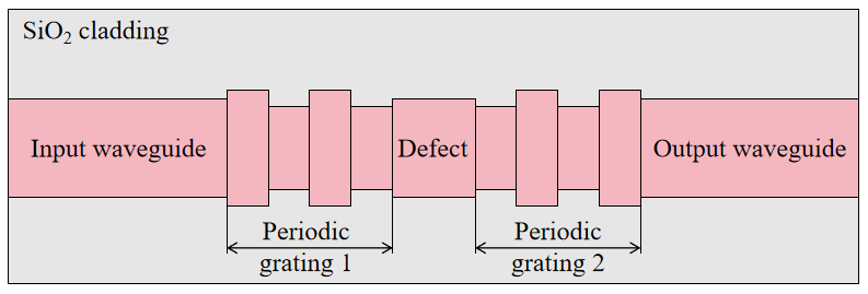
The phase-shifted Bragg grating simulated in this example consists of a silica cladding, an input waveguide, periodic grating sections, a defect, and an output waveguide. The defect is located at the center of the structure to introduce a phase shift. The grating section is formed by the periodic arrangement of two sub-units that are identical except for their lengths, and the two periodic grating sections are mirror-symmetric with respect to the defect, as shown in the figure below. The phase-shifted Bragg grating can be regarded as a Fabry–Pérot (F-P) resonant cavity, where the phase-shifted region (defect) acts as the cavity and divides the grating into two parts, forming the two reflective end faces of the resonant cavity.
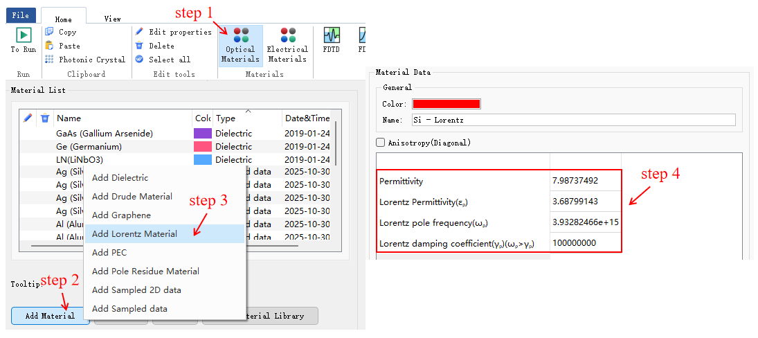
The silica cladding uses a Dielectric material with a refractive index of 1.444; the grating material is Si established by a Lorentz model. The Lorentz model is a typical dispersive material model, using the dielectric constant to represent the Lorentz material model. For a single-pole () Lorentz material, the relationship between the dielectric constant and frequency is:
In the material library window, add a Lorentz material model via Add Material > Add Lorentz Material, modify the material parameters in the pop-up editing interface to complete the creation of the Lorentz material model. The specific parameters and creation steps are shown in the figure below. For details on the Lorentz model, please refer to Lorentz Material.
Solver Settings
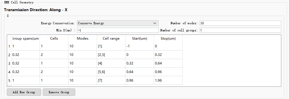
In the EME solver settings, five cell groups are defined. Cell groups 1 and 5 are the input and output waveguides, and cell group 3 is the central defect that induces the phase shift. The cross-sections of these three cell groups remain unchanged, and one cell is sufficient for solving. Cell groups 2 and 4 are the periodic gratings on both sides, each composed of two structures corresponding to two different sub-units. In addition, each cell group uses 10 modes for calculation, taking advantage of the structural symmetry to reduce the required number of modes. The specific settings are shown in the figure below.
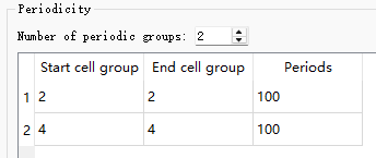
To set the periodicity of the grating, two periodic groups are defined in the Periodicity table, corresponding to the periodic gratings on both sides of the defect. The number of periods for both groups is set to 100, as shown in the figure below. Cell groups 2 and 4 are repeated for 100 periods each, resulting in a total device length of 66.32 μm.
Simulation Results
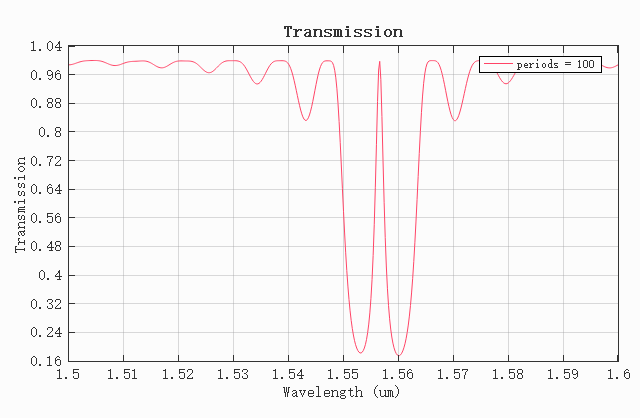
Since EME is a frequency-domain method, one simulation needs to be run for each wavelength of interest. Therefore, we provide the Phase_shifted_Bragg_grating_EME.msf script as a demonstration. Open the attached Phase_shifted_Bragg_grating_EME.mpps project, run the script to perform the simulation, calculate the grating transmittance in the wavelength range of 1.5 to 1.6 μm, and plot the transmission spectrum. The figure below shows the transmission spectrum of the phase-shifted Bragg grating when the number of periods is 100. A distinct transmission window can be seen in the stopband, which is consistent with the results in reference [1].
Since changing the number of periods does not require recalculating the modes, only the number of periods of the two periodic groups needs to be modified. Through wavelength sweep, the transmission spectra of the phase-shifted Bragg grating for any number of periods can be quickly obtained, with extremely short computation time. Change the Flag_singleperiod value in the script to 0 and rerun the Phase_shifted_Bragg_grating_EME.msf script. The results are shown in the figure. As the number of periods increases, the transmission window in the stopband becomes sharper; when the number of periods is very large, the transmission window eventually disappears. This is because an increase in the number of periods enhances the reflectivity of the grating and the quality factor of the resonant cavity, but at the same time increases the cavity loss, making the transmission window eventually indistinguishable.

References
[1] P. Prabhathan, et al., "Compact SOI nanowire refractive index sensor using phase shifted Bragg grating," Opt. Express, 17(17), 15330-15341 (2009).