

Vortex Beam Metasurface
Preface
A metasurface is a structure composed of periodically arranged subwavelength units. Its working principle is based on the generalized Snell's law, and it can manipulate electromagnetic wave propagation by designing specific phase gradients. Compared with traditional optical devices, metasurfaces have advantages such as being ultralight, ultrathin, and easy to integrate. They can flexibly adjust the amplitude and phase of light beams, and are widely used in polarization conversion, beam shaping, and other fields. Based on reference [1], this example uses the finite-difference time-domain (FDTD) method to model and simulate a metasurface composed of a V-shaped antenna array, successfully generating a vortex beam carrying orbital angular momentum, and uses far-field projection to obtain the intensity distribution and interference pattern of the beam at 50 wavelengths behind the metasurface.
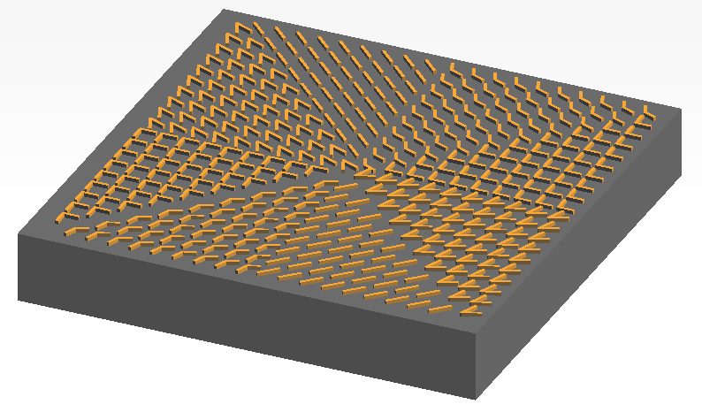
Simulation Settings
Structure Model
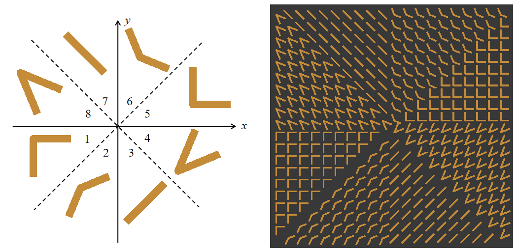
The basic structural unit of the metasurface is a V-shaped antenna, which consists of three parts: two rectangular metal arms with a certain angle between them and a cylinder connecting the two arms. The arm width is , the arm height is , and the cylinder radius is . The material is set to Au (Gold) - Palik. When -polarized linearly polarized light is incident, the two arms of the V-shaped antenna are excited simultaneously, producing a scattered field polarized along the direction, as well as a cross-polarized scattered field polarized along the direction due to structural asymmetry. By adjusting the geometric parameters of the V-shaped antenna, the phase delay of this cross-polarized component can be precisely controlled while keeping the scattering amplitude essentially unchanged.
To achieve uniform coverage of the phase from to , a total of 8 V-shaped antennas with different arm lengths (), different angles between the two arms (), or different overall rotation angles () are selected, so that the phase difference between adjacent elements is . The specific parameters of the antennas are shown in the table below.
| Antenna | |||
|---|---|---|---|
| 1 | 90 | -45 | 1.1 |
| 2 | 135 | -45 | 0.9 |
| 3 | 180 | -45 | 0.8 |
| 4 | 45 | 45 | 1.3 |
| 5 | -90 | 45 | 1.1 |
| 6 | -135 | 45 | 0.9 |
| 7 | 180 | 45 | 0.8 |
| 8 | 45 | -45 | 1.3 |

The metasurface is formed by a periodic arrangement of V-shaped antennas, with a lattice constant (center-to-center distance between adjacent antennas) of . To achieve the helical phase gradient required for a vortex beam, the plane is divided into 8 equally spaced sector regions centered at the origin, each corresponding to . V-shaped antennas with specific parameters are placed in different regions, so that the phase difference between adjacent regions is , thereby forming continuous phase coverage from to in space. In addition, to reproduce the metasurface in reference [1] and avoid non-physical scattering caused by excessive phase jumps, antenna elements near the diagonal of the third quadrant are removed when setting the antennas, as shown in the figure below.
In the FDTD solver, all boundary conditions are set as perfectly matched layers (PMLs) to absorb incident and reflected electromagnetic waves at the simulation boundaries. Since the antenna size is small, to ensure calculation accuracy, a custom mesh is added in the antenna region, and the mesh size in all three directions is set to .
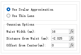
Since the boundary condition is PML, a plane-wave source cannot be used in the project (a plane-wave source would diffract at the PML edge). To simulate a normally incident uniform plane wave, a Gaussian source with a central wavelength of is used as the incident source, and its parameters are further set as shown in the figure below. The waist width is set to , and the distance from the injection plane to the waist (distance from waist) is set to , ensuring that the incident light has an approximately flat wavefront and uniform intensity distribution in the central region of the metasurface.
Simulation Results
Due to strong localized surface plasmon resonance (LSPR) and evanescent wave coupling in the near-field region of the metasurface, the phase distribution of the near-field wavefront is highly disordered, and the central phase singularity is easily obscured by stray components. According to diffraction propagation theory, when the light field propagates to the far field (Fraunhofer region), the transmitted light field can escape near-field perturbations. Therefore, to observe and analyze the vortex beam generated by the metasurface, its far-field distribution needs to be obtained. In FDTD simulations, there are two common approaches for obtaining the far-field distribution of a device: one is to directly expand the simulation region so that light propagates to the target position. Although this method is intuitive, its computational cost is high. The other is the near-field-to-far-field transformation, which does not require expanding the simulation domain and is suitable for quickly estimating far-field results.
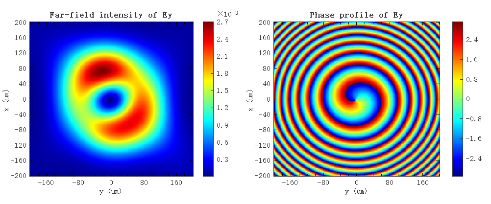
Open the attached vortex_beam_metasurface.mpps project and run the simulation. After the simulation, run the vortex_beam_metasurface.msf script. Based on the data recorded by the near-field monitor, the script calls the farfieldeql2d function to project the electric field onto the far-field plane at a distance of 50 wavelengths (i.e., ) from the metasurface, and plots the intensity distribution and phase distribution of the cross-polarized component () of the transmitted light on the far-field plane, as shown in the figure below. The figure shows that the far-field intensity of the transmitted light is ring-shaped, with a dark core of zero intensity at the center of the beam; the phase exhibits a continuous spiral distribution around the central singularity from to , and the accumulated phase change after one full circle around the center is , which is a typical phase characteristic of a vortex beam. The simulation results show that the transmitted beam carries orbital angular momentum, and the zero intensity at the center is caused by the phase singularity generated by the helical phase on the beam axis.
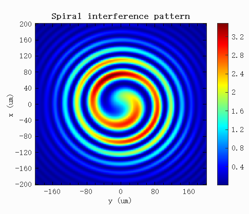
To visualize the wavefront characteristics of the vortex beam, the far-field-generated vortex beam is superimposed with a co-propagating Gaussian reference beam through interference, and the result is shown in the figure below. When a vortex beam carrying a helical phase is superimposed with a flat-phase reference beam, their complex amplitudes interfere, producing spiral interference fringes. This type of fringe pattern is a typical characteristic produced when a vortex beam undergoes coaxial interference with a co-propagating reference beam.
Appendixes
Generalized Snell's law
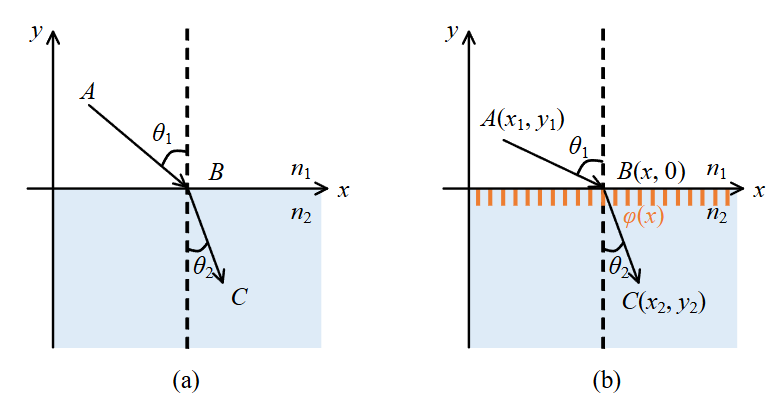
Fermat's principle states that light traveling from one point to another, regardless of how many times it undergoes refraction and reflection, has an optical path that is an extremum. During light propagation, when light travels from one medium into another uniform medium with a different refractive index, refraction occurs at the interface between the two media, as shown in figure (a) below.
Snell's law, derived from Fermat's principle, can be used to determine the propagation direction of the refracted ray, and its expression is:
where and are the refractive indices of the media, and and are the angles of incidence and refraction.
If a subwavelength antenna array with negligible thickness is added at the interface between the two media, this antenna array introduces a phase discontinuity at the interface, whose magnitude depends on the position . The traditional Snell's law is no longer applicable and needs to be rewritten. Later research led scientists to extend it, explaining the anomalous phenomenon caused by phase discontinuities rather than phase accumulation in metasurfaces, and named it the generalized Snell's law.
The generalized Snell's law is the basic working principle of metasurfaces and can still be derived from Fermat's principle. As shown in figure (b) above, assume that the interface between the two media is the -axis and the normal is the -axis. When light enters medium 2 (refractive index ) from medium 1 (refractive index ) at an angle of incidence , it travels from through to , and its optical path is
where , .
Since there is an additional phase that varies with position along the -axis at the interface, the optical path changes, and the above equation becomes
where is the wavelength of the incident light.
According to Fermat's principle, the optical path corresponding to the path from point through point to point is an extremum, so the first derivative of the optical path with respect to should be zero, i.e., the following condition is satisfied:
In the Cartesian coordinate system,
Thus, the expression of the generalized Snell's law can be obtained:
The formula shows that to control the propagation path of the light beam, one can control the additional phase introduced by the metasurface, thereby controlling the angle of refraction and achieving precise control of the light beam.
References
[1] N. Yu, et al. "Light Propagation with Phase Discontinuities: Generalized Laws of Reflection and Refraction," Science, 334(6054), 333-337 (2011).