

Reflection and Transmission Calculations Using a Plane Wave
Preface
For laterally uniform multilayer structures with refractive index variations only in the thickness direction, the stack script provides an efficient analytical calculation method. Based on the transfer matrix method (TMM), the stack script associates each layer with a transfer matrix, multiplies the matrices sequentially to obtain the overall transfer matrix, and finally solves for the reflectance, transmittance, and field distribution of the structure. Using a four-layer dielectric structure as an example, this page compares the transmittance and reflectance at different incident angles obtained from the stackrt script and the FDTD simulation. In addition, the stackrt script is used to analyze the effect of a 5 nm thickness variation in the middle layers on the reflectance.
Simulation settings
Device introduction
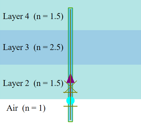
As shown in the figure above, a plane wave with a wavelength of propagates along the positive y‑axis from air (Air, ) and is incident upon a stack composed of three dielectric layers with refractive indices of , , and , respectively. The thicknesses of Layer 2 and Layer 3 are both .
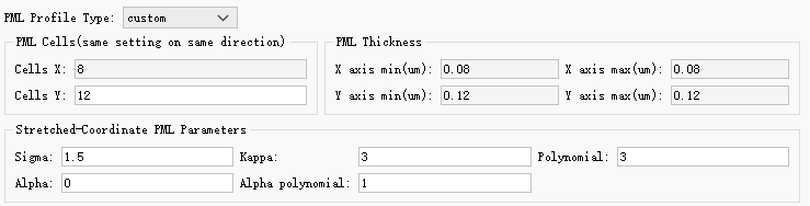
The simulation uses uniform mesh with a mesh size of . For boundary conditions, Bloch boundary conditions are applied in the x‑direction to model a laterally infinite planar structure. In the light propagation direction (y‑direction), PML boundary conditions are used. To prevent reflections from the PML when the incident light is obliquely incident, the PML profile type is set to custom with the specific parameters shown below.
This example presents results for s‑polarization (electric field perpendicular to the plane of incidence). Results for p‑polarization can be obtained by simply adjusting the polarization setting.
Simulation Results
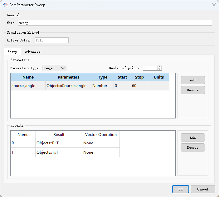
In the FDTD simulation, each simulation provides results at only a single incident angle; therefore, parameter sweep is required to obtain the transmittance and reflectance as a function of angle. Note that when the structure is complex or the mesh is fine, the parameter sweep can be time‑consuming. The attached project planewave_4layer.mpps includes a pre‑configured parameter sweep with 30 points, scanning the incident angle from to , as shown in the figure below.
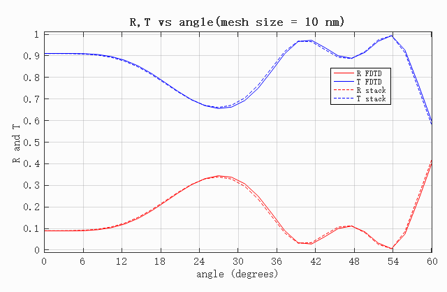
After running the attached script planewave_4layer.msf, the script plots the transmittance and reflectance obtained from both the FDTD simulation and the stackrt script command. As shown in the figure, the FDTD results agree well with the stackrt results overall, though some deviations remain at certain angles. In addition, the script also shows the maximum and minimum reflectance variation predicted by stackrt when the thickness of the middle two layers is varied by .
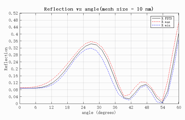
The core script commands for calculating transmittance and reflectance using stackrt are shown below. It can be seen that after defining the refractive indices, layer thicknesses, frequency, and incident angles, only three lines of script are needed to quickly compute the transmittance and reflectance for all angles—simple, user‑friendly, and efficient.
RT_stack = stackrt(n,d,f,theta);
R_stack = RT_stack.Rs;
T_stack = RT_stack.Ts
To further improve the agreement between FDTD and stackrt, the mesh size is reduced to and the number of parameter sweep points is increased to 60 to smooth the curves. The results are shown below. It is evident that with a finer mesh, the FDTD results approach the analytical stackrt results more closely.
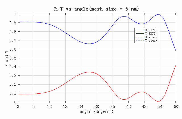
The stack script functions do not require mesh generation, offer fast computation and high numerical accuracy, and are particularly suitable for parameter sweeps and optimization iterations. By simply inputting the refractive indices, thicknesses, frequency, and incident angle of each layer, results can be obtained quickly, making them ideal for rapid preliminary assessments in applications such as thin‑film design, VCSELs, OLEDs, and Bragg grating mirrors.