

Photonic Crystal Slab
Preface
A photonic crystal is an artificial microstructure whose dielectric constant is periodically distributed in space. Its period is comparable to the wavelength of light, allowing effective control of light propagation. Among them, two-dimensional photonic crystal slabs have become an important platform for integrated photonic devices because they are compatible with semiconductor planar processes. However, the finite thickness of a photonic crystal slab in the vertical direction introduces guided-mode resonance effects, making its transmission and reflection spectra highly sensitive to the frequency, incident angle, and polarization state of light. This characteristic provides a solid physical basis for wavelength selection and optical field manipulation.
This case is based on the two-dimensional photonic crystal slab structure model in Ref. [1]. The rigorous coupled-wave analysis (RCWA) method is used to simulate its reflection and transmission characteristics. In addition, a convergence test is performed to determine the influence of the maximum number of k-vectors on computational accuracy, and the application potential of photonic crystals in wavelength selection and angle tuning is verified.
Simulation Settings
Structure Setup
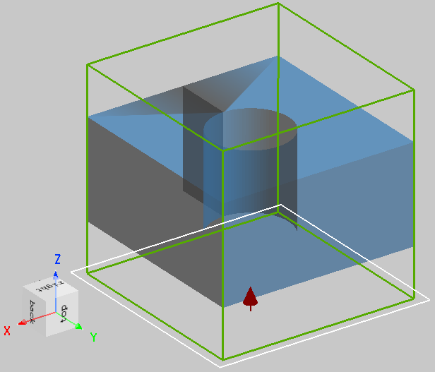
The photonic crystal slab used in this case is a square-lattice photonic crystal with circular holes. In the simulation, only one unit cell is modeled, i.e., a unit containing a single circular hole, as shown in the figure below. The thickness of the photonic crystal slab is 0.5 μm, the period of the photonic crystal is 1 μm, and the refractive index of the medium is 3.4641.
Light Source Setup
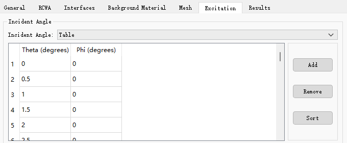
As shown in the figure above, the incident light propagates along the positive z-axis. In this case, the incident angle mode Incident Angle of the RCWA solver is set to Single or Table to analyze the transmission and reflection characteristics under different incidence modes. The relevant setup windows are shown in the figures below. The normalized frequency range of the incident light is 0.5–0.55. The normalized frequency is expressed as:
where f is the frequency, a is the period of the photonic crystal, and c is the speed of light.

Simulation Results
Run the script file photonic_crystal_slab.msf in the project file photonic_crystal_slab.mpps. The script will enable the RCWA solver, solve the transmission and reflection characteristics of the photonic crystal slab, and determine the influence of the maximum number of k-vectors on computational accuracy through a convergence test.
Transmission and Reflection Characteristics at Normal Incidence
The figure below shows the transmittance and reflectance as functions of normalized frequency at normal incidence. Due to the symmetry of the geometric structure, the results for P polarization and S polarization are identical at normal incidence, so only a single polarization state is shown.
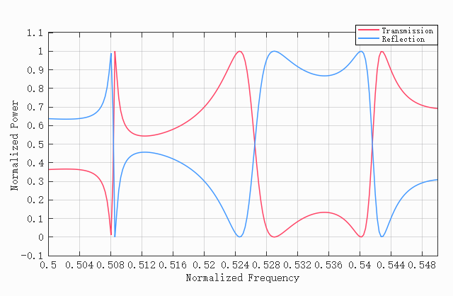
It can be seen that the transmission and reflection spectra are highly sensitive to frequency. This is because, when the phase-matching condition is satisfied, light is coupled into the slab and excites guided modes. The light leaking from the guided modes to the upper and lower sides (i.e., the transmission side and the reflection side) interferes with the directly transmitted and reflected light. The resonance is highly sensitive to frequency, and a slight shift in the peak position can cause a large change in transmittance.
Determining the Influence of the Maximum Number of k-Vectors on Computational Accuracy Through a Convergence Test
In the RCWA method, the electromagnetic field is expanded as a superposition of a series of plane waves, which correspond to different discrete components in k-space. In k-space discretization, the larger the maximum number of k-vectors, the higher the simulation accuracy, but the computation time also increases accordingly. Therefore, a convergence test is needed to achieve a balance between accuracy and computational cost.
By sweeping the Max Number K Vectors property of the RCWA solver, the influence of the maximum number of k-vectors on computational accuracy can be examined. Subsequently, the script extracts the frequencies corresponding to three peaks in the transmission spectrum and calculates their relative errors with respect to the approximately converged peak positions in Fig. 8 of Ref. [1]. The reference values of the three peaks are taken as 0.5058, 0.526, and 0.542, respectively. The relative error σ is defined as:
where is the frequency of the peak in the simulation result, and is the approximate frequency of the peak in Ref. [1]. The results are shown in the figure below:
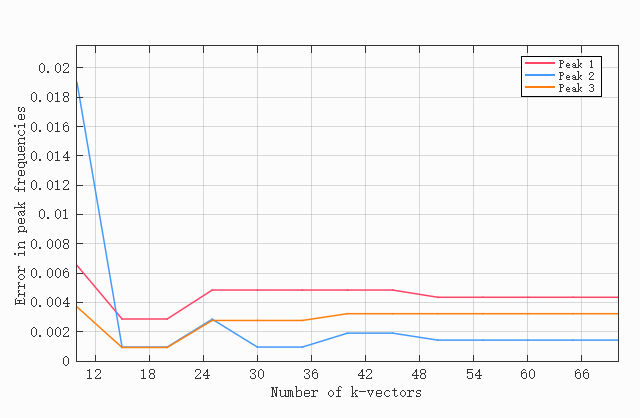
It can be seen from the figure that, as the maximum number of k-vectors increases, the peak positions gradually converge to values highly consistent with those in Ref. [1]. The accuracy of the RCWA simulation improves as the maximum number of k-vectors increases, so this trend is consistent with expectations.
Transmission Characteristics at Oblique Incidence
Based on the convergence test results in the figure above, the maximum number of k-vectors Max Number K Vectors is set to 15 to achieve a balance between accuracy and simulation time. The figures below show two-dimensional distributions of transmittance for P polarization and S polarization as functions of normalized frequency and incident angle over the incident angle range of 0°–30°.
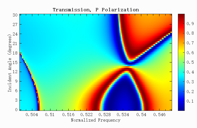
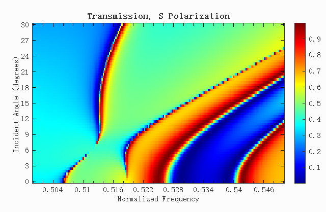
It can be seen from the figures that the transmission characteristics depend simultaneously on frequency, incident angle, and polarization state. This is because the phase-matching condition of guided-mode resonance is related to the incident angle, and a change in angle changes the wavelength required for resonance. In addition, the transmission spectra of P polarization and S polarization are significantly different, and the positions and intensities of the resonance peaks evolve differently with angle, indicating that the structure is selective with respect to polarization state and has application potential in angle tuning and polarization splitting.
References
1.V. Liu and S. Fan, "S4: A free electromagnetic solver for layered periodic structures," Comput. Phys. Commun. 183, 2233-2244 (2012)