
Application Gallery
OLED
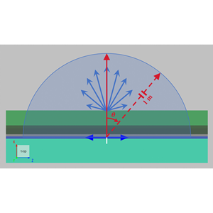
Organic light-emitting diode (OLED) devices are widely used in high-end displays and solid-state lighting due to their self-emissive nature, wide viewing angle, high contrast ratio, and compatibility with flexible form factors. A typical OLED consists of multiple organic functional layers and electrodes, with a total thickness usually on the sub-micrometer scale. In such a multilayer optical environment, radiation generated by dipole emitters in the emissive layer is strongly influenced by optical confinement and interference effects. In addition, refractive index discontinuities between functional layers cause a large portion of the emitted light to be trapped inside the device in the form of waveguide modes or surface plasmon polariton modes, so that only a small fraction can escape into air. As a result, accurate modeling of multilayer optical behavior, combined with micro- and nanostructure design to enhance light extraction efficiency (LEE), is a key challenge in OLED optical design. In this case, a 2D FDTD method is used to model an OLED device. By comparing structures without microstructures and with periodic microstructures (photonic crystals), the effect of microstructure design on LEE is evaluated.

Fresnel Lens
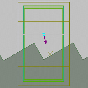
By employing a distinctive “concentric stepped ring” structure, the Fresnel lens decomposes the continuous surface of a conventional lens into multiple “annular micro-lenses,” each functioning as an independent refracting surface. This design dramatically reduces the lens thickness and mass while maintaining focusing or imaging performance comparable to that of a traditional convex lens. Because of this thin and lightweight architecture, Fresnel lenses are widely used in lighthouse illumination, projection systems, solar concentrators, and compact imaging devices—particularly in applications where high focusing efficiency is required under tight volume and cost constraints. In this case, a 2D FDTD simulation is performed for a Fresnel lens derived from a spherical lens profile, demonstrating its wavefront-shaping capability and characteristic phase behavior.
Blazed Grating
The blazed grating is a specially optimized diffractive structure designed to efficiently direct most of the incident light energy into a designated diffraction order by introducing a blaze angle on the grating surface. This significantly improves diffraction efficiency while suppressing unwanted orders. In this case study, an `FDTD` simulation is performed on a blazed grating to analyze its energy distribution among different diffraction orders.
Bulls eye aperture
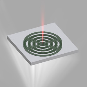
The bull’s-eye aperture is a metallic subwavelength optical structure characterized by a central circular hole surrounded by periodically distributed concentric grooves. When incident light illuminates the metal surface, the concentric slits excite surface plasmon polaritons (SPPs) at specific wavelengths, which are re-radiated through the central aperture to the opposite side, resulting in strong transmission and significant field enhancement. In this case study, a bull’s-eye aperture fabricated on a silver film is simulated to demonstrate its characteristic field enhancement and directional radiation effects.
Using grating projections calculate fields at an arbitrary location
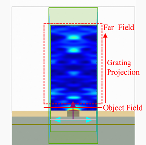
In FDTD simulations, obtaining the field distribution at locations far from a device usually requires expanding the simulation domain so that light can fully propagate to the target plane. While this approach is straightforward, it significantly increases computational cost and simulation time. This case presents a Grating Projection(GP)–based approach that can quickly obtain the distribution of fields propagating in homogeneous media at any specified location, and verifies its accuracy through comparison with FDTD simulation results.
Diffraction Grating
The Diffraction grating is a classic type of periodic optical element, widely used in fields such as spectroscopy, laser beam control, and beam splitting. Their functionality relies on spatially modulating the wavefront of incident light to generate a series of discrete diffraction orders in specific directions. Since a grating's performance is governed by its diffraction-order energy distribution, precise quantification of this distribution becomes critical for design optimization. This case demonstrates how to use the grating projection functions in an FDTD simulation of a two-dimensional periodic grating, allowing for accurate evaluation of the energy distribution among diffraction orders and their corresponding efficiencies.
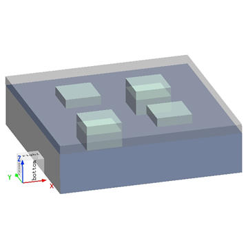
Lithography Using Alternating Phase Shift Mask
The demand for smaller, faster, and lower power semiconductor devices continuously drives advances in optical lithography technology. As the size of semiconductor devices continues to shrink, it is necessary to use alternating phase shift masks (APSM) to improve resolution. For example, at the 45nm node, some features to be imaged are smaller than the diffraction limit of the 193nm light source used. APSM modulates the phase so that the light interferes with itself after passing through the mask, making the mask pattern edges sharper and clearer, thereby improving pattern contrast. The proximity effects occurring at sub-wavelength scales need to be understood through lithography simulation, so they can be accounted for in mask design, ensuring a predictable and reliable process. This case demonstrates how to image sub-wavelength features using APSM in FDTD.
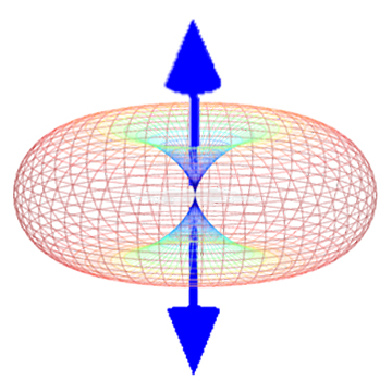
Mie Scattering from a Dielectric Sphere
Mie scattering is an effect that occurs when particles have a size comparable to or larger than the wavelength of the incident light. In this case, we use SimWorks Finite Difference Solutions to calculate the scattering field of a nanoparticle excited by a Total-field Scattered-field(TFSF) light source. The built-in analysis group of Far field from a closed box is then employed to compute the far-field scattering distribution of the particle.
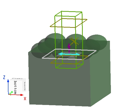
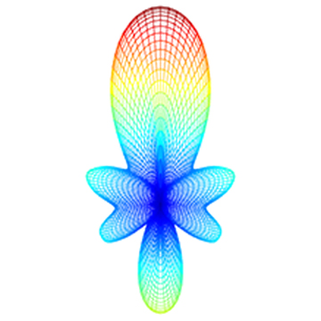
Far Field Analysis - Directivity
As defined by IEEE, “Directivity” is the ratio of the radiated power in the specified direction to the average radiated power in all directions. Directivity, obtained from further analysis of the far field, is one of the important parameters describing the far field radiation characteristics. You can use the Directivity analysis group to compute directivity.