不同材料的多结构重合处的折射率分布为什么与我预想的结果不同? #
问题描述 #
当多个不同材料的结构在某处重叠时,我发现仿真区域内的折射率分布与预期结果不一致,无法正确体现结构间的重叠或刻蚀关系,如下图所示。我应该如何排查和修正软件的设置?
可能的原因 #
当不同材料的多个结构重合在某处时,需要用户设置各结构的材料优先级,如果不手动设置优先级,软件会默认按照文件树的结构顺序来确定优先级。因此当结构的 Mesh Order 错误时,就可能使得部分结构的材料被覆盖。
解决方案 #
问题排查 #
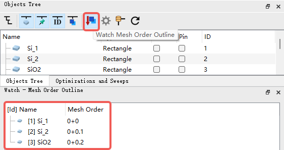
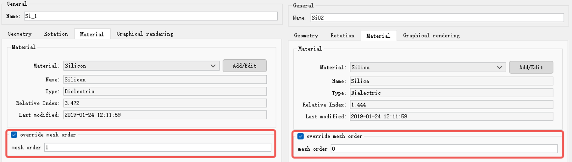
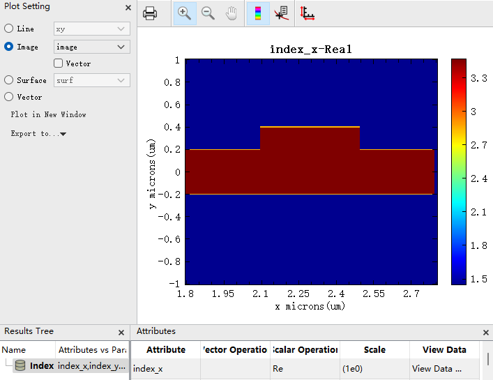
1. 在结构树中检查各结构的 Mesh Order 数值,当数值越高表明优先级越高,高优先级的结构在结构重合处会覆盖掉低优先级结构的材料。如下图中所示,SiO2结构拥有最高的优先级,在结构重合处会覆盖掉两个Si结构的材料分布。
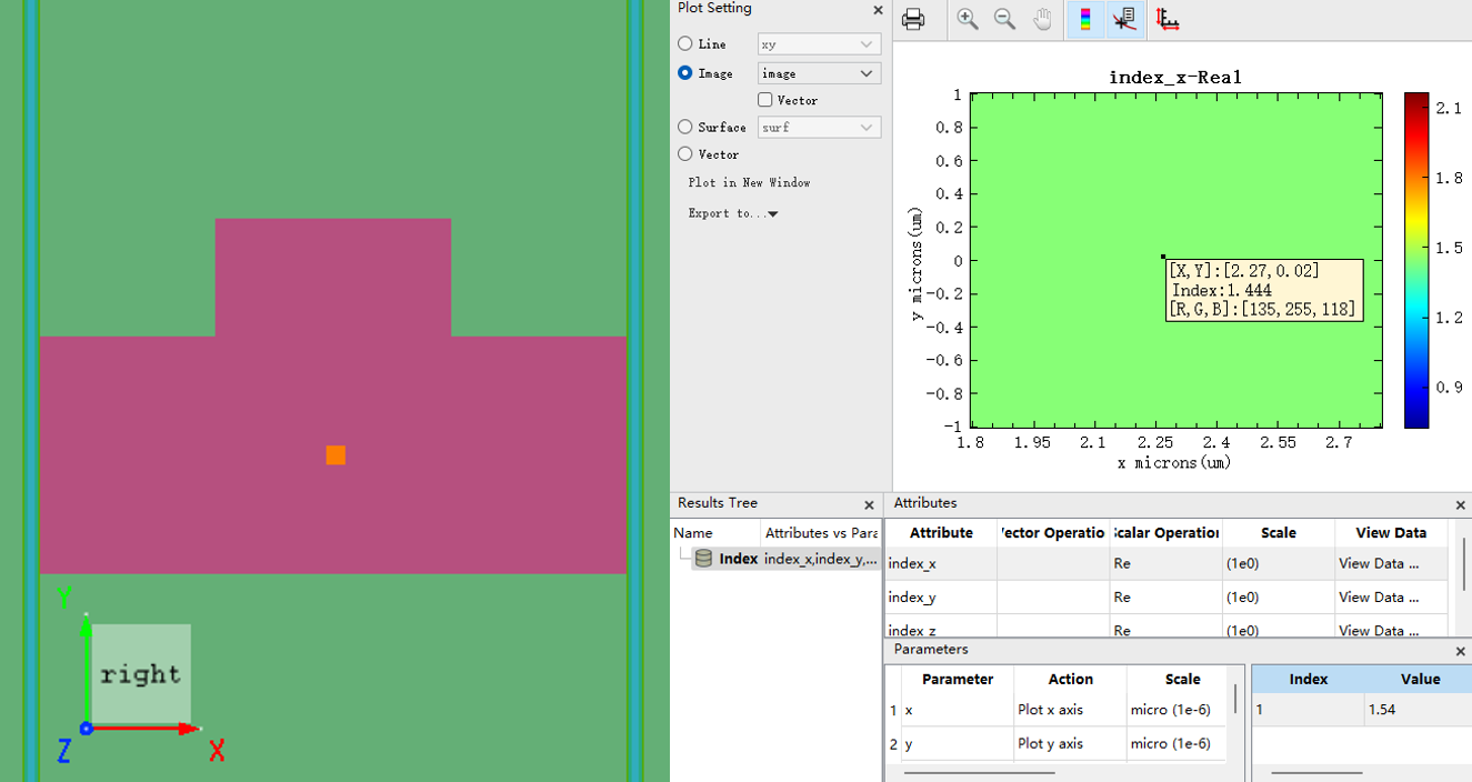
2. 检查Index监视器内的相对折射率分布。检查Index监视器是最直观有效的方法,如上图中的折射率分布,在衬底结构( SiO2 )中未观察到对应刻蚀 Si 材料的折射率分布。可以确定是结构的 Mesh Order 设置错误。
解决方法 #
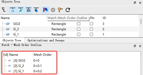
1. 按照需求重新排列结构在结构树中的顺序。如在本问题当中,将衬底SiO2结构拖动到结构树第一个顺序,即可得到正确的 Mesh Order 。
2. 手动按需求设置各结构的 Mesh Order 等级。在结构属性页中找到 Override Mesh Order 选项并设置对应的 Mesh Order 数值。在本问题中,需将 Si 材料的优先级设为最高,使它能覆盖衬底 SiO2 材料,以实现 “刻蚀” 的效果。如下图所示,将 Si 的 Mesh Order 设为 1(高于 SiO2 的 0),则在折射率分布中 Si 材料会覆盖衬底的 SiO2 材料。
对于复杂不同材料的多结构构建, Mesh Order 的设置非常重要。例如下图,通过合理设置 Mesh Order 可以在两种基底材料中“挖出”两个空心半球孔。此外还需要注意2D材料的 Mesh Order 等级为最高,无法被其他结构覆盖。
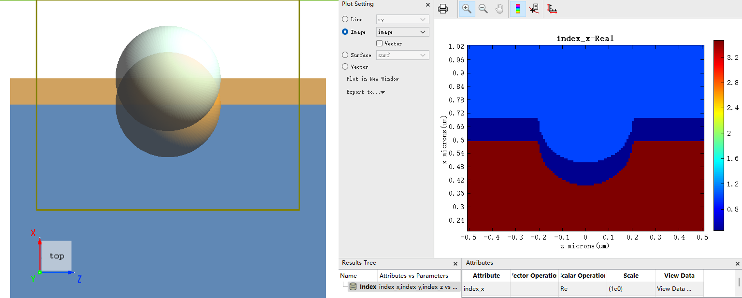
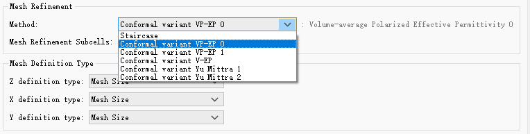
3. 需要说明的是,多材料边界处的共形网格折射率分布会根据所选网格细化方式生成。具体而言,这种结构边界处生成的共形网格折射率是一种数值上的近似,因为共形网格折射率是根据一个网格中多种材料的比例进行的某种加权平均得出的。详细说明请参见官网知识库中网格细化部分。以本问题中Index监视器中的折射率分布为例, Si 与 SiO2 材料交界处的折射率分布,展示了采用软件默认VP-EP0细化方式生成的共形网格折射率计算结果。用户可根据实际需求选择合适的网格细化方式。