Contact Number
Email
 Enterprise WeChat
 WeChat Service Account
This section explains the user mesh.
User mesh is supported in all algorithms (FDTD, FDFD, and FDE).
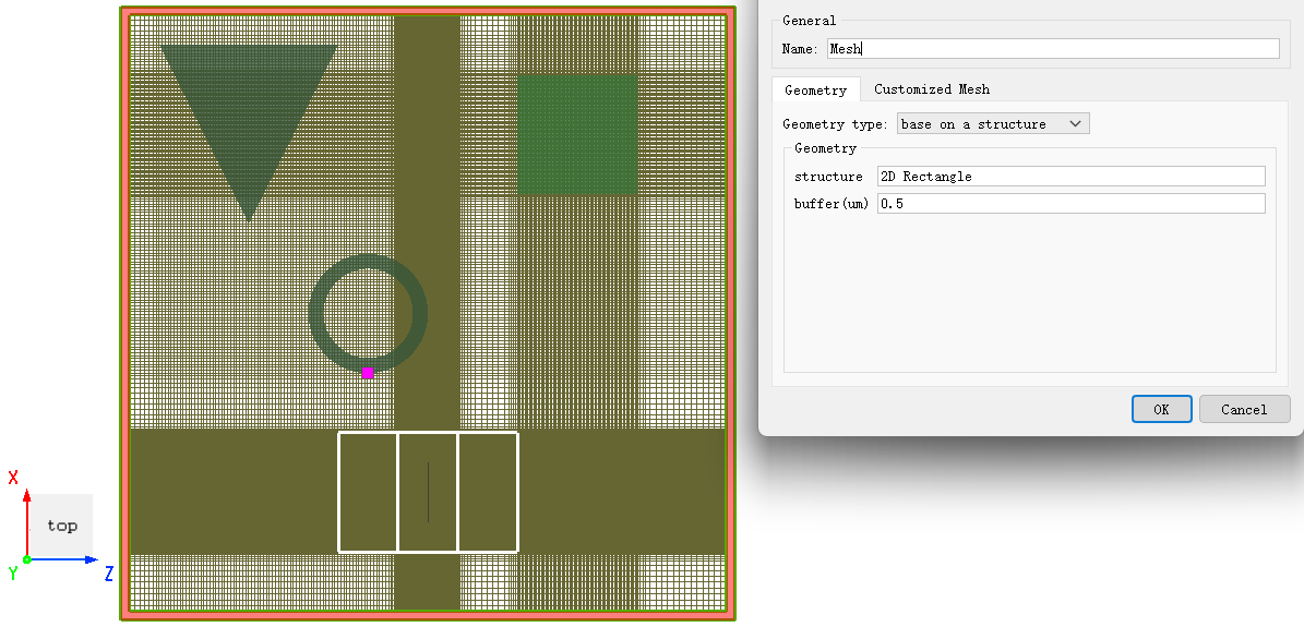
Select Mesh in solver tab. Next, create user mesh in Composite viewer. In Edit properties interface that is displayed automatically, modify settings of user mesh. Finally, user mesh is added completely.
User mesh belongs to one of the advanced features of the software.
User mesh is used to override original Mesh in the simulation space.
Usually, mesh partitioning parameters are set on Mesh tab of Solver page. If some simulation areas require further mesh partitioning, user mesh is used.
If there are multiple user meshes intersecting, the mesh partitioning algorithm uses the smallest mesh step size within the intersection space.
In addition, Solver>Mesh>Min mesh size setting has the highest setting level. That is, mesh will be created according to the value of Min mesh size setting if the user mesh is smaller than the minimum mesh size.
You can view mesh partitioning results easily in View simulation mesh. For related operations, see Quick Access Toolbar.
This tab is used to set the spatial geometry parameters of the user mesh, including position and range. Users can choose between two definition methods: Directly defined and Base on structure.
When selecting Directly defined, users can manually set the center position and coverage range of the mesh.
| Name | Description |
|---|---|
| X/Y/Z pos | Set the center coordinates of the user mesh. |
| X/Y/Z span | Set the coverage range of the user mesh in each direction. |
When selecting Base on structure, users can define the coverage range and position of the user mesh based on existing structures or structure groups.
| Name | Description |
|---|---|
| Structure | Enter the name of an existing structure or structure group (case-sensitive). The center coordinates of the user mesh will be based on the center position of the specified structure. |
| Buffer | Buffer area, enter a non-negative value. The system will expand the mesh range outward in the X/Y/Z directions based on the minimum and maximum positions of the specified structure by the buffer value. The default value is 0. |
Set mesh partitioning according to the following types:
| Name | Description |
|---|---|
| Maximum mesh size>dx/y/z | Define step size on x/y/z axis for the type set in Maximum mesh size. |
| Equivalent index>Equivalent index x/y/z | Define equivalent index in x/y/z direction for the type set in Equivalent index. |
Consider the following relationships for user mesh:
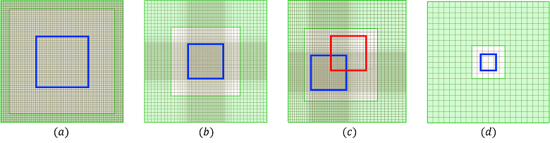
Mesh partitioning results of some cases are displayed as follows:
| Number | Description |
|---|---|
| Use Mesh of Uniform type to add a user mesh. The mesh size inside and outside user mesh will be consistent to ensure the uniformity of the mesh throughout simulation space. Note: (1) Compare values of Solver mesh and user mesh, and select smaller step size to partition simulation space. | |
| Use Mesh of Auto nonuniform type to add a user mesh. Simulation space is partitioned non-uniformly. This is the most common case of user mesh. Note: (1) Priority of user mesh is always higher than of simulation setting. | |
| When user meshes intersect, intersected part uses minimum mesh step size to partition simulation space. | |
| When unit size of user mesh is smaller than Solver>Mesh>Min mesh size setting in a certain axis direction, software uses data of Min mesh size setting to create a uniform mesh in that axis direction, i.e., Min mesh size setting has the highest priority. |
To view and get actual data of mesh partitioning, see Mesh, etc.
