总场散射场光源的设置
总场散射场光源的设置 #
本节是关于总场散射场光源设置的介绍。
在研究散射场的问题时,可以使用总场散射场(Total-Field Scattered-Field, TFSF)光源直接获取散射场。
在求解器选项卡中选择TFSF,在复合视图中创建TFSF光源,在自动弹出的编辑属性界面中设置参数。
TFSF 光源 #
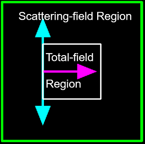
在FDTD中,TFSF光源将计算区域分为两个不同的区域:
- 总场Etotal=Einc+Escat,即总场Etotal等于入射场Einc加上散射场Escat之和;
- 散射场区仅包括散射场Escat。
TFSF光源通常用于研究散射问题和天线问题。典型用途包括:
- 均质介质中的颗粒(可能是有损的或各向异性的),例如三重散射;
- 多层基板中的非周期性结构,可以是有损的或各向异性的;
- 多层基材中的周期性结构,当与周期性或 Bloch 边界条件结合使用时。
TFSF光源是高级光源,用户必须根据本说明确定光源设置的合理性,从而保证所得结果的正确性,否则错误设置可能导致结果错误。
TFSF 光源的设置 #
通用设置 #
General选项卡用于设置光源的注入轴和振幅等信息。
| Name | Description |
|---|---|
| Incident axis | 下拉选择TFSF光源的注入轴。 |
| Direction | TFSF光源的传播方向,Forward为正向传播,Backward为反向传播。 |
关于TFSF光源振幅、相移和旋转的设置,请参阅光源的通用设置。
几何尺寸 #
Geometry标签页用于设置光源的几何尺寸,请参阅光源的几何尺寸设置。
偏振 #
Polarization标签页用于设置光源偏振。
| Name | Description |
|---|---|
| Linear polarization(θ) | 线性偏振的偏振角。 |
波长/频率 #
Wavelength/Frequency标签页用于设置光源的波长/频率信息,请参阅光源的波长/频率设置。
TFSF光源的注意事项 #
用户在使用TFSF光源时应当遵循以下注意事项,以避免TFSF光源设置中的常见错误,确保仿真结果的准确性和可靠性。
TFSF光源的结构设置 #
在添加TFSF光源时,请确保以下条件:
- 散射体必须完全位于TFSF光源内;
- 光源的波矢必须垂直于基板。换句话说,TFSF光源的所有侧面都必须沿传播方向“看到”相同的折射率分布。
下文中展示了一个有效设置示例和一个无效设置示例。
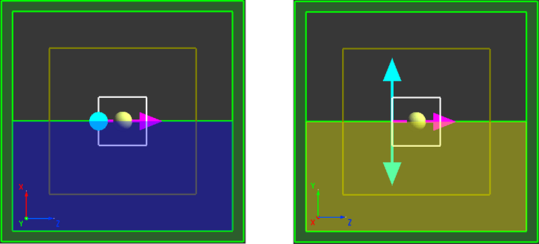
有效注入:光源的波矢垂直于金层和玻璃层。光源的每一面沿传播方向(从注入面到端面)“看到”相同的折射率分布(空气-金-玻璃)。
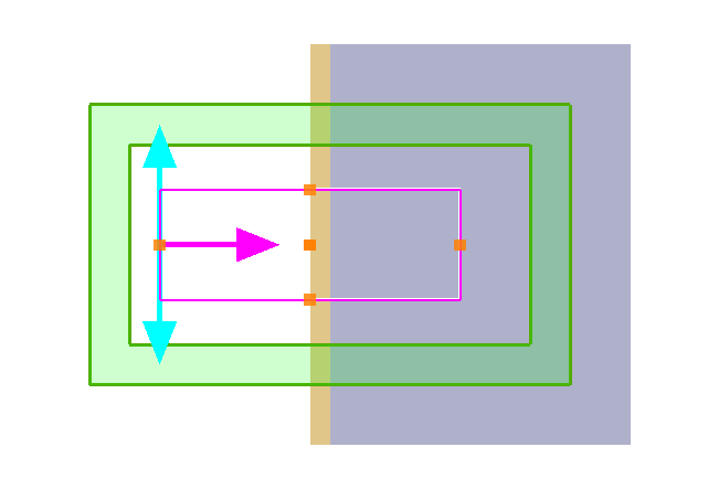
无效注入:光源的波矢与基板不垂直。光源的上方“看到”空气的折射率,而下方“看到”衬底的折射率。
TFSF光源的内部结构,我们可以分为以下两种情况:
-
- TFSF光源内为同一介质;
-
- TFSF光源内有不同介质:目前仅适用于传播方向介质一致的场景,比如多层材料,暂时不支持TFSF光源内包含不同介质的复杂分布。
以下将对上文中的两种情况进行详细描述:
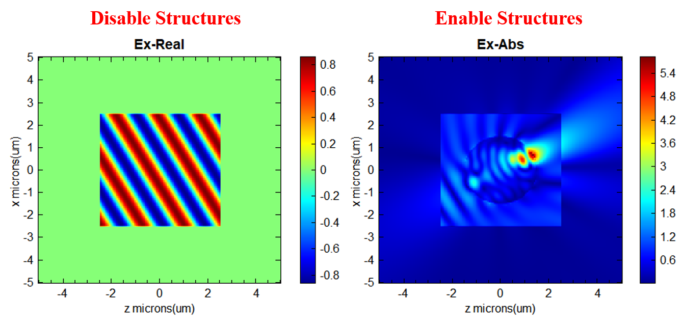
1. 对于TFSF光源内部仅有一种介质,TFSF光源支持任意角度入射。
建议用户在进行斜入射仿真前,可先禁用材料结构以检查TFSF光源设置是否正确,再进行下一步仿真。两者的仿真结果如下图中所示。禁用结构后,TFSF光源在真空中传播,电场只集中分布在TFSF区域内(即总场内),散射场几乎为0。
2. 在多层材料仿真中,各材料层的法线方向必须与总场散射场(TFSF)光源的注入平面保持垂直。因此,模拟斜入射时,只允许改变光源的入射角度,而严禁改变材料层的放置方向。在此设置下,透过衬底的传播场将被严格限定在总场区域内,无法作为散射场穿过TFSF边界。在下图所示的多层硅-二氧化硅结构斜入射仿真中,电磁场被TFSF边界完全吸收,实现了与散射场区域的完全隔离。

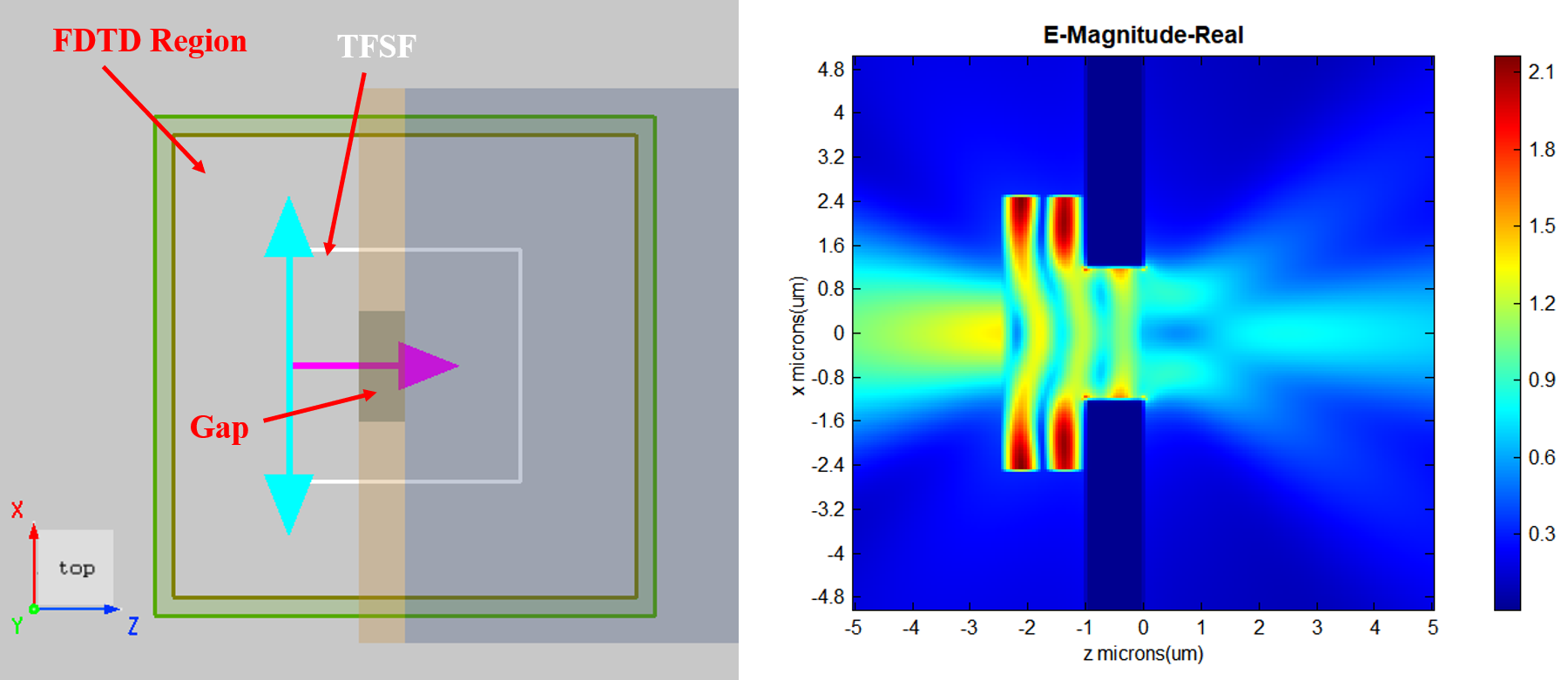
此外,在上图中的空气-金-玻璃层的仿真中,如果在金层中间增加一个间隙,散射光可以通过间隙进入散射场区域。该间隙视为散射体,应完全位于TFSF光源内部。
目前,TFSF光源已支持在任意入射角度下使用非均匀网格进行仿真。若仿真结果出现异常,建议用户可以尝试切换至均匀网格进行排查,以排除网格因素带来的干扰。
TFSF光源跨越边界 #
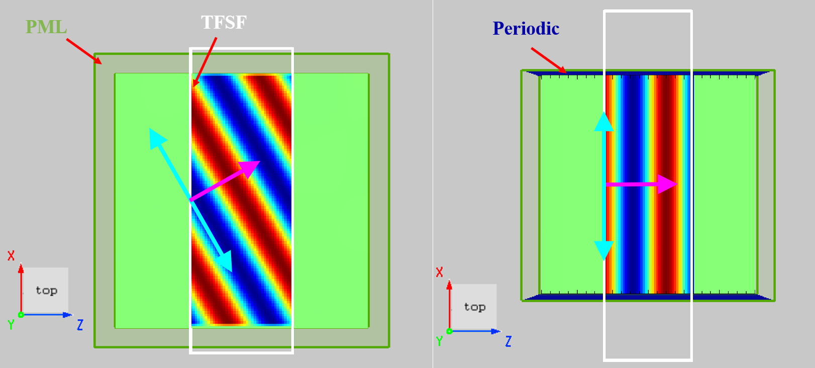
一般情况下,TFSF光源不应跨越仿真区域边界,下面2种情况除外:
- 在PML边界处,软件会自动将光源约束在PML边界内,即TFSF光源仅在PML边界内部生效。
- 使用周期边界时,TFSF光源应当跨越该边界。同样支持跨越Bloch边界。
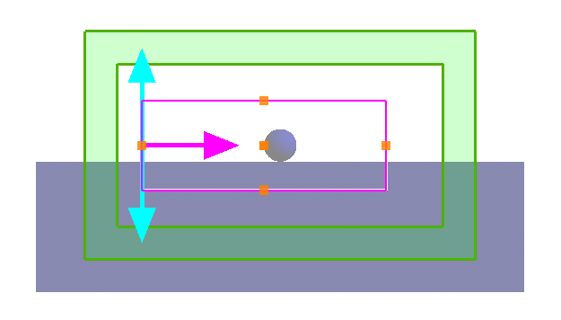
案例:介质球的米氏散射 #
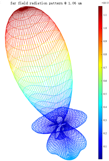
使用TFSF光源研究介质球的米氏散射,相关内容请参阅介质球的米氏散射,工程为:
仿真结束后,提取散射场(TFSF光源包围空间外的场),使用远场分析,即可得到极坐标图、辐射图: