介质球的米氏散射
前言
米氏散射是一种粒子尺度接近或大于入射光波长时发生的散射效应。其散射的光强在各个方向是不对称的,其中大部分入射光线沿着入射光前进的方向进行散射。本案例使用FDTD建模仿真计算了一个由总场散射场光源激发的纳米粒子,并使用软件内置的封闭盒外的远场far field from a closed box分析组计算了该粒子的远场散射分布。
仿真设置
模型简介
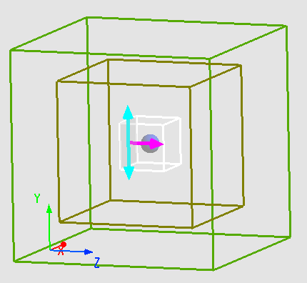
本案例中使用总场散射场(Toal-Field Scattered-Field)TFSF光源激发一个直径为 ,折射率 的介质小球。由于小球是中心对称且光源在 方向上对称,在 方向上反对称,所以 方向使用对称Symmetric边界条件, 方向使用反对称Anti-symmetric边界条件。
光源设置
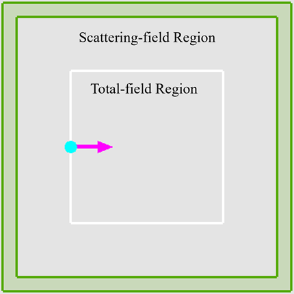
TFSF光源分为两部分,在光源的包围框内是总场区域,在光源的包围框外是散射场区域,如下图。在总场区域包含了入射场和散射场,TFSF光源的入射场相当于一个平面波,在散射场区域中仅包含散射场 。因此在散射场区域放置监视器可以剔去入射场从而直接研究散射场。由于米氏散射需要粒子的尺度与入射光波长接近,所以TFSF光源使用 的波长入射。
封闭盒外的远场分析组
根据表面等效原理,计算某散射体的远场投影,必须计算其每个方向上的近场贡献。因此本软件内置了“封闭盒外的远场”分析组,该分析组由频域场-能量FDFP监视器组成一个封闭的盒子,用来记录散射体外所有方向上的近场值。再根据线性叠加原理就可以求得任意散射体在指定的远场观察位置处的场分布,即实现对任意散射体的近场到远场的投影。
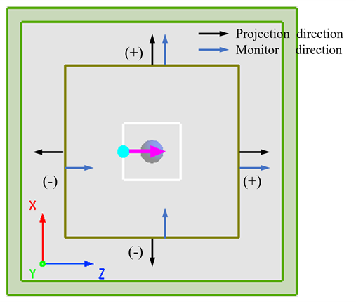
散射体远场投影的线性叠加规则如下图。取封闭盒子的外表面法线作为正方向。因此,对于封闭盒子的外表面法线与FDFP监视器的定义方向相同时取正号,反之取负号。
注意:FDFP监视器组成的盒子必须封闭,须保证所有源和结构被囊括其中,不能存在与盒子相切或者穿越盒子表面的光源或者结构。
仿真结果
近场结果
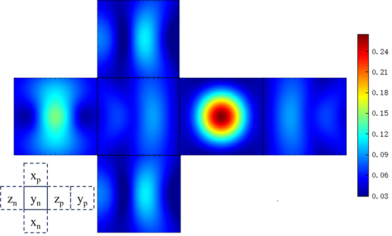
从分析组的FDFP监视器中,可以得到粒子的散射场在封闭表面上的电场分布。这里封闭表面是立方体的六个面,再将各个表面的电场分布按照空间位置展开如下图所示。附件工程中使用了对称和反对称边界条件, 监视器不在仿真区域内,没有仿真结果,其电场分布可以分别从 监视器中对称得到。从图中可以看到,光源沿着 轴正向传播并激发介质球后,封闭盒子表面的 监视器得到的散射光强最大。
远场结果
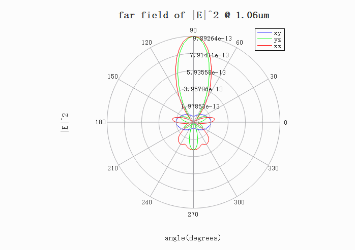
仿真结束后,运行Far field from a closed box分析组的分析脚本,将FDFP监视器中得到的近场数据投影至远场。分析组缺省的远场投影位置为半径 的圆上,远场投影可以被修改到任意空间位置(只需满足远场条件)。下图为 面内半径 的圆上得到的远场分布图,可以看出在 轴正方向的散射最强,符合米氏散射中散射场主要集中在光源传播方向的特点。
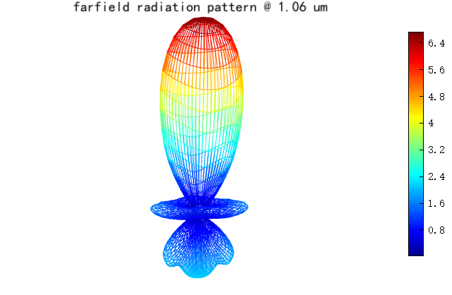
运行Directivity分析组的脚本可以绘制出介质球米氏散射的三维远场辐射图如下,可以直观地看出介质球的散射方向为 轴正向。