光学介电材料、nk材料和电导材料
介电材料、(n, k)材料和电导材料 #
本节是关于介电材料、(n, k)材料和电导材料的介绍。
介电材料 #
介电材料是无色散的,材料参数仅由折射率n确定,与频率/波长无关(即对所有频率的响应相同)。
尽管Kramers-Kronig关系指出,材料折射率的虚部k不可能在所有频率上为0(意味着无损),但介电材料可以近似地描述具有恒定折射率(非色散)的材料。
介电材料的相对折射率n必须大于等于 1。
| Name | Symbol | Range | Default | Description |
|---|---|---|---|---|
| Relative index | n | n≥1 | 1 | 相对折射率,用来描述具有恒定折射率的无色散材料。 |
材料设置 #
材料库中包含了几种常见的介电材料,用户也可以通过Add material>Add new material>Add dielectric添加所需的介电材料。
添加对角各向异性的介电材料,需要勾选Anisotropy(Diagonal),并分别设置每个方向的相对折射率。
更多信息请参阅光学材料的空间特性部分。
更多信息 #
用户自定义的介质 #
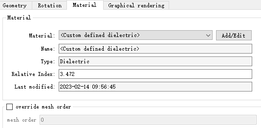
由于介电材料极为简单且常用,在结构编辑页面,允许用户对结构的折射率快捷赋值。
在结构的属性编辑窗口,切换到材料页面,选择自定义介电材料,即可在折射率输入框中输入所需的材料折射率n。
(n, k)材料 #
(n, k)材料适用于单频点仿真,使用复折射率N定义材料的n和k。
N=n+iκ
其中,n为N的实部,表示相对折射率;κ为N的虚部,表示衰减。
| Name | Symbol | Range | Default | Description |
|---|---|---|---|---|
| Relative index | n | 实数,n≥0 | 1 | 复折射率N的实部。 |
| Imaginary relative index | κ | R | 0 | 复折射率N的虚部。 |
材料设置 #
在材料库窗口,通过Add material>Add new material>Add (n, k) material添加(n, k)材料模型,在弹出的窗口修改材料参数,完成(n, k)材料模型的创建。
更多信息 #
(n, k)材料的宽频仿真 #
(n, k)材料只用于单频仿真。如果应用于宽频仿真,只能保证中心频点处的折射率正确。
电导材料 #
电导材料模型使用复介电常数εtotal表示。其中,复介电常数εtotal与频率f的关系为:
εtotal=ε+i2πfε0σ
其中,ε为介电常数,σ为电导率,单位为(Ω.m)−1。
| Name | Symbol | Units | Range | Default | Description |
|---|---|---|---|---|---|
| Permittivity | ε | ~ | 实数,ε≥1 | 1 | 介电常数 |
| Conductivity | σ | (Ω.m)−1 | 实数,σ≥0 | 0 | 电导率 |
材料设置 #
在材料库窗口,通过Add material>Add new material>Add conductive添加所需的电导材料, 在编辑界面修改材料参数。
更多信息 #
PEC #
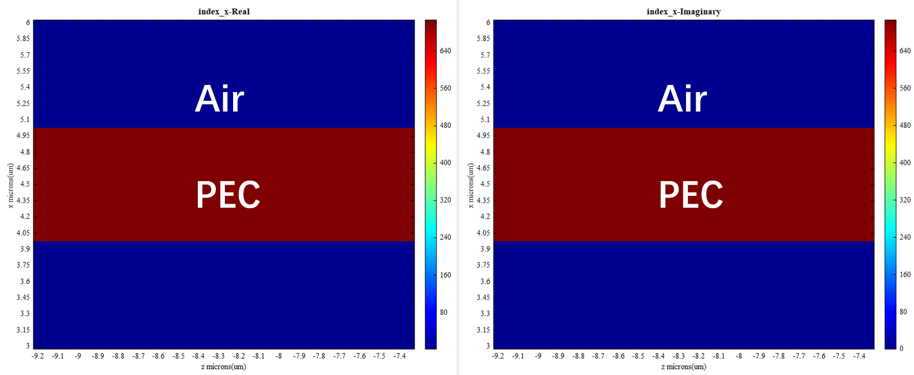
当电导率σ设置得非常大时,电导材料模型的性能接近理想的导体,即PEC材料。
PEC材料除材料的名称和颜色外无其他设置参数,PEC材料的折射率如下图:
2D电导材料 #
除了一般的电导材料,软件还支持2D电导材料。
在材料库窗口,通过Add material>Add new material>Add Conductive 2D添加所需的2D电导材料。
2D电导材料的表面电导率是材料的体电导率(σ)和材料厚度(t)的乘积。
| Name | Symbol | Units | Range | Default | Description |
|---|---|---|---|---|---|
| Layer thickness | t | m | 实数,t≥0 | 3.5e-5 | 二维材料的物理厚度 |
| Conductivity | σ | (Ω.m)−1 | 实数,σ≥0 | 58000000 | 材料的体电导率 |