如何同时对工程中多个参数进行扫描? #
问题描述 #
在实际工程中,由于参数之间可能相互关联,我需要同时扫描多个参数,以分析这些参数对仿真结果的综合影响。我应该如何在软件中高效地实现多参数的联合扫描。
可能的原因 #
软件中的参数扫描功能可用于分析参数对仿真结果的影响,帮助用户找到满足目标要求的最优参数或关键结构参数。扫描过程中,软件会根据参数扫描目标值自动建模并运行仿真,并保存每次仿真计算的工程文件及结果。用户还可以通过软件的预处理和后处理脚本,实现更复杂的参数扫描需求。针对多参数扫描,软件提供了多种方法进行设置。
解决方案 #
问题排查 #
软件支持多种多参数扫描方式:
1. 设置非嵌套扫描时,可同时添加多个参数,但需要确保这些参数的样本点数量相同。
2. 设置嵌套扫描时,需注意每个嵌套扫描层级中的名称不能重复。
3. 通过脚本命令实现参数扫描。该方式需要用户熟悉相关脚本命令的使用方法。
解决方法 #
以下对上述方法进行详细说明:
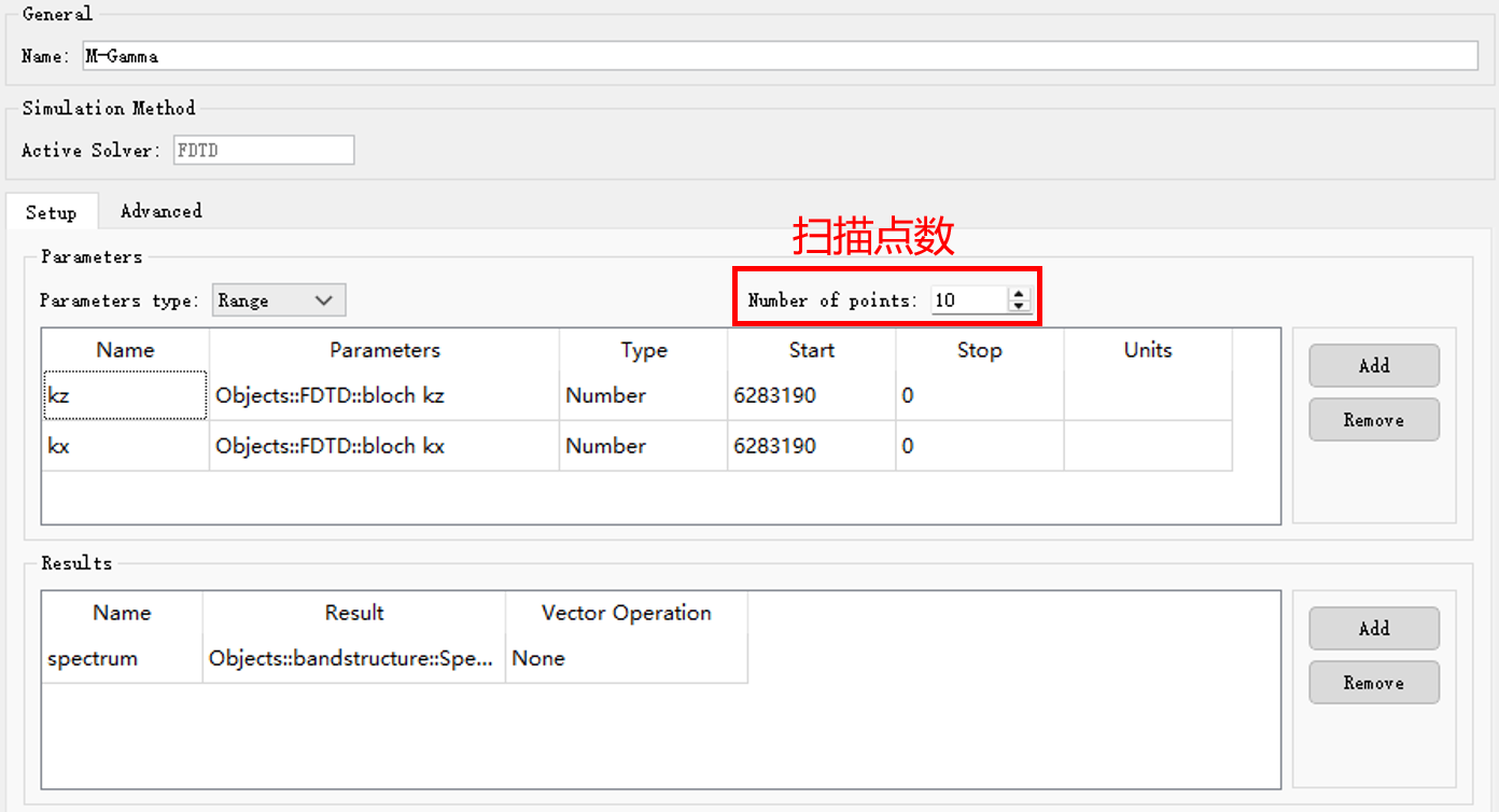
1. 在设置非嵌套扫描中,可以在一次扫描中同时添加多个参数,这些参数需要拥有相同数量的样本点。每次扫描将按照每个参数设置的一列数值来同步更新所有的参数。具体设置请参见扫描设置。
如下图所示,光子晶体在周期方向上对bloch波矢进行扫描时,每次扫描会根据[kz,kx]每一列的数值来更新工程的仿真设置。
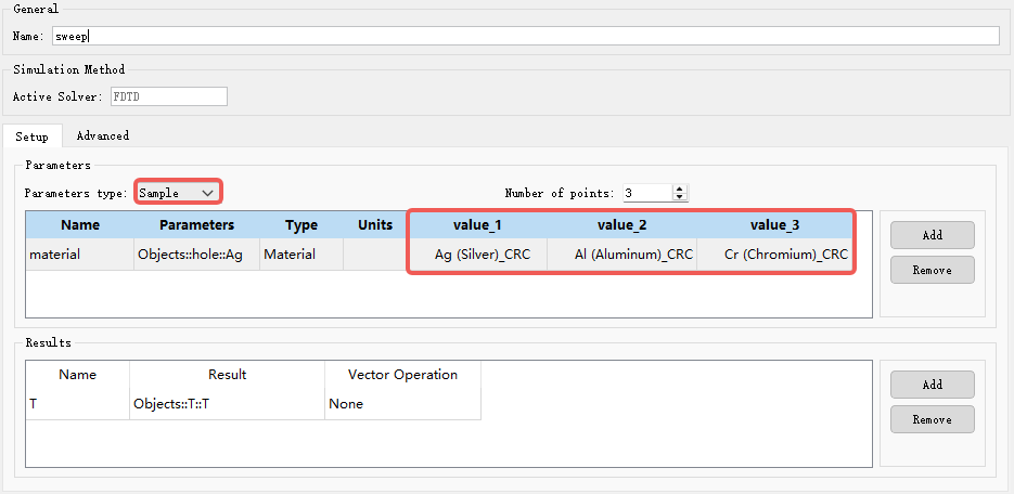
用户还可以将Range切换为Sample模式,输入特殊参数的离散样本值。下图展示了材料参数的扫描设置。
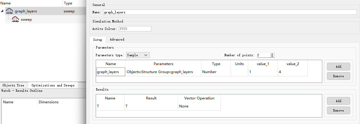
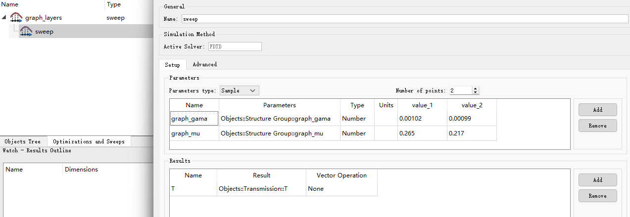
2. 多参数扫描还可通过嵌套扫描功能实现。每次嵌套扫描将外层扫描的某一参数与所有内层扫描参数组合为一组,依次进行扫描。例如,在基于石墨烯的可调谐太赫兹超材料案例中,需要按照下表探究石墨烯层数与费米能级之间的关系时,可采用嵌套扫描。
| Number | Scattering Rate(Γ) | Chemical Potential(μc/eV) | Temperature(T/K) | Conductivity Scaling(c) |
|---|---|---|---|---|
| 1 | 0.00102 | 0.265 | 300 | 1 |
| 2 | 0.00102 | 0.265 | 300 | 4 |
| 3 | 0.00099 | 0.217 | 300 | 1 |
| 4 | 0.00099 | 0.217 | 300 | 4 |
以上嵌套扫描包含两层:外层为石墨烯层数的参数扫描,内层为化学势和散射率组成的多参数扫描。当石墨烯Conductivity Scaling设置为一层时,依次扫描所有Chemical Potential相关的参数。依次类推,再扫描石墨烯为四层时的参数。具体设置方法请参考嵌套扫描。
3. 在更复杂的多参数扫描场景下,还可以通过脚本命令来实现。
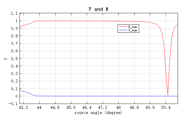
在在石墨烯中激发表面等离子体案例中,面对非线性和多数量参数变化的需求,用户可以参考以下脚本实现参数扫描。以下展示了通过脚本命令建立光源入射角度的参数空间,然后在for循环中使用setnamed设置光源参数,调用run运行仿真,并使用getdata获取每次扫描的结果。相关脚本命令可在知识库脚本命令中查阅。
## 建立光源角度扫描参数
src_theta_TIR = (43.0:0.1:43.9)';
src_theta_rest =(44.0:1:48.0)';
src_theta_dip = (49:0.1:51)';
TIR_len = length(src_theta_TIR);
rest_len = length(src_theta_rest);
dip_len = length(src_theta_dip);
theta_len= TIR_len+rest_len+dip_len;
src_theta(1:TIR_len) = src_theta_TIR;
src_theta(TIR_len+1:TIR_len+rest_len) = src_theta_rest;
src_theta(TIR_len+rest_len+1:theta_len) = src_theta_dip;

for I=1:theta_len
    ## 修改工程光源对应参数
    setnamed("FDTD::Plane Source","angle",src_theta(I));

    ## 运行工程
    run();
    ## 获取结果
    R_num(I) = abs(getdata("FDTD::back","T","T"));
    T_num(I) = abs(getdata("FDTD::front","T","T"));

    E_x=squeeze(getdata("FDTD::field","E","Ex"));
    E_y=squeeze(getdata("FDTD::field","E","Ey"));
    E_z=squeeze(getdata("FDTD::field","E","Ez"));

    E_image=abs(E_z).^2+abs(E_x).^2+abs(E_y).^2;
end