色散材料FDTD仿真发散,如何避免发散? #
问题描述 #
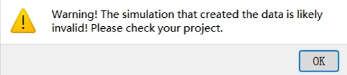
在仿真含有色散材料的结构时,软件有时会提示"仿真发散"并提前终止计算。我发现仿真运行一段很短的时间后,仿真区域的能量值在短时间内急剧增大,导致仿真自动终止。请问如何调整设置,才能避免这种发散现象,得到正确的仿真结果呢?
可能的原因 #
大多数发散问题源于仿真区域的能量超过设定阈值,导致软件提前终止仿真并提示发散。这类问题主要分为两类:一是网格尺寸或者时间步长设置错误,不满足Courant稳定条件而引发发散;二是PML边界条件相关的问题。
解决方案 #
问题排查 #
基于以上可能问题的描述,可通过两种方法确认问题:
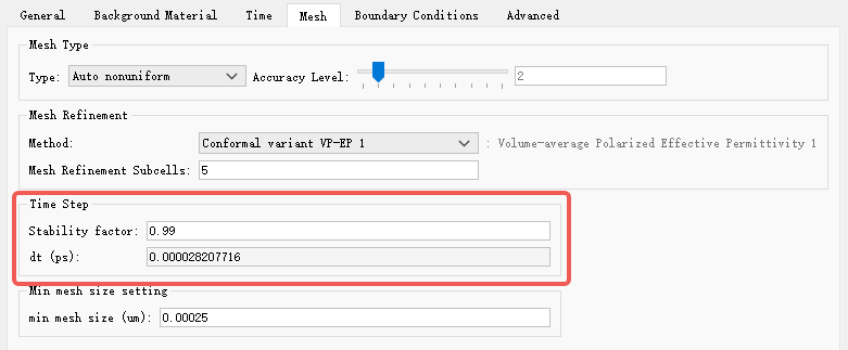
1. 根据Courant稳定条件,计算当前仿真的网格尺寸( Δx )或者时间间隔( Δt )是否满足该条件。3D网格下该稳定条件为:
Δt≤c(Δx1)2+(Δy1)2+(Δz1)21
通常来说,当用户设置均匀网格大小或者使用自定义网格时,有可能出错,建议按照公式检查参数并修改。
对于时间步长,如果计算结果不满足上述条件,可以减小 Stability Factor 。通过逐步减小该因子直至仿真收敛。多数情况下,0.95或0.9的取值即可使仿真稳定。在某些情况下,可能需要0.5或更小的值。减小时间稳定因子虽然不会影响仿真精度和内存需求,但会增加仿真时间。
这种方法无法解决第二类发散问题。
2. 对于第二类发散问题,可将所有边界条件由PML改为PEC,并重新运行仿真:如果仿真仍然发散,可以按照第一类发散问题去排查;如果仿真收敛,则可确定为PML相关的发散问题。
解决方法 #
第一类发散的问题的解决方法比较简单,可以参考上述说明;第二类发散问题的成因更为复杂,解决方法也分为多种情况,详情参见以下描述:
1. 色散材料穿过PML边界时,可能引发仿真稳定性问题并导致发散。通常,我们会将物理结构延伸穿过边界条件(BC)区域,以获得最准确的仿真结果。但部分色散材料在穿越PML边界时可能不稳定,场将会在色散材料与PML边界的接触点开始发散。此现象可以通过动态时域场显示功能来观察。具体解决办法如下:
1) 让色散材料不接触或穿过PML层,使得结构至少离开边界一个网格的距离,且取消勾选 Extend Structure through PML 选项。此操作有可能会使PML边界的反射增加。
2) 将PML设置为 Stabilized ,该设置通常可解决仿真发散问题。与 Standard 设置相比,此选项增加了PML的层数和Alpha值。这一设置将会增强PML边界的吸收能力,同时也会增加仿真所需的计算资源和运行时间。

3) 如果方法 2) 仍无法解决发散问题,可以进一步将PML设置为 Custom ,手动增加层数和Alpha值。但通常不建议对PML设置不熟悉的用户使用。
4) 增大PML边界前的网格尺寸。在垂直PML表面方向上增加网格间距,可提升PML的吸收稳定性。但这可能对计算精度以及PML的吸收效率产生影响。
2. 色散材料的拟合结果中出现非物理增益。若拟合结果中存在场增益的部分时,会导致仿真计算发散。具体表现为介电常数(或相对折射率)的虚部存在负值。此时需要检查当前工程中所使用材料的拟合曲线:在仿真波段中,若介电常数(或相对折射率)虚部的拟合曲线存在负值区间,则表明存在非物理增益。解决方法为调整仿真波段或者优化拟合参数,重新拟合至虚部无负值即可。
同理,也可以使用Index监视器检查整个仿真区域的折射率分布,观察折射率虚部是否存在负值。