软件运行时显示仿真资源的内存不足,如何解决? #
问题描述 #
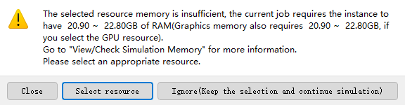
在进行仿真计算时,软件有时会弹出“仿真资源的内存不足”的提示,如下图中所示。软件也会在运行过程中因内存超限问题导致仿真中断。为确保仿真能够顺利进行,我应当采取什么样的优化措施来避免这些情况的发生?
可能的原因 #
仿真计算中影响内存占用的因素主要包括三方面:网格剖分内存、仿真运行内存以及数据处理内存:
a 网格剖分过密:导致网格矩阵所需内存超过计算资源配置的内存上限。
b 仿真运行内存开销过大:包含光源多频域采样点过多,以及仿真中使用的色散材料过多等。
c 数据处理量过大:监视器记录及分析组数据处理环节需要存储和处理的数据量过大。
解决方案 #
问题排查 #
SimWorks软件具有 Check Simulation Memory 功能,用户可以在对应知识库中仿真前的内存预览找到对应说明。使用该功能可以查看当前工程的内存占用,如下图中所示:
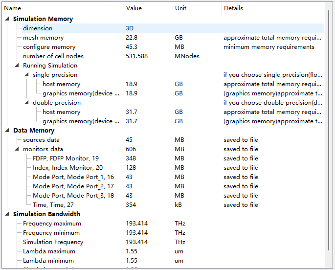
从上图 Memory Report 可以看到 Mesh Memory 占用达到了22.8GB,超出当前计算资源16GB的内存空间上限。同时 Running Simulation 内存占用也达到了18.9GB,同样超过了可用内存空间。仅 Data Memory 占用较少。
解决方法 #
对于问题 a ,减小网格剖分密度的具体操作如下:
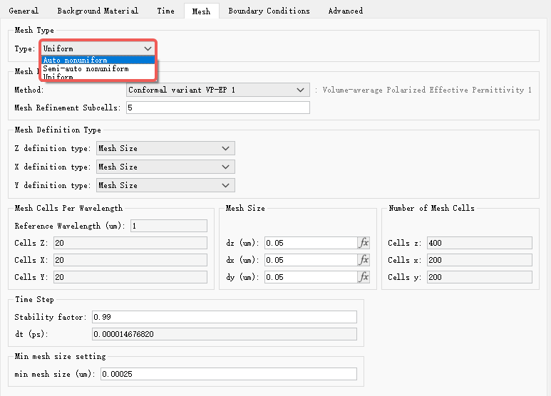
1. 当前如果是 Uniform 网格,推荐首先使用 Auto Nonuniform 网格进行初步仿真,这不仅能够大大减少仿真所需内存和仿真时间,而且能够确定大致的仿真结果和趋势是否正确。
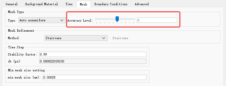
2. 当前如果是 Auto Nonuniform 网格,在不影响计算结果的情况下,可以将 Accuracy Level 设置小一些。建议设置在2~4这个范围内获得精度与速度的平衡。
3. 了解FDTD网格划分原理的高级用户,可以采用 Semi-Auto Nonuniform 或者 Auto Nonuniform 结合局部自定义 Mesh 的方式来进行网格划分。
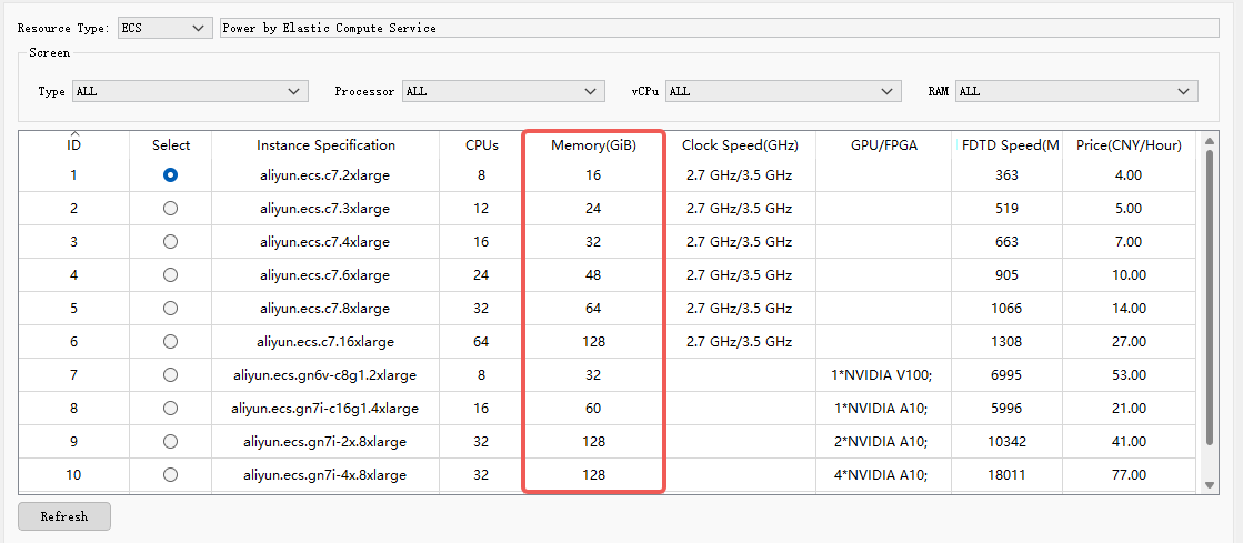
4. 当您确定 Auto Nonuniform 的初步仿真趋势正确,继续使用 Auto Nonuniform + 局部自定义 Mesh 进行仿真结果优化时,如果依然显示内存不足,最简单直接的办法是选择内存空间足够大的资源进行仿真。
对于问题 b 和 c ,软件默认设置下内存一般占用较低,在不影响所需仿真结果的前提下,可按以下步骤减小内存占用:
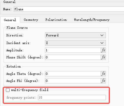
1. 光源参数优化:
如果您使用多频点光源的设置,减少宽带光源的多频域采样点数量。该选项默认未勾选,仅在宽带光源非正入射场景下建议启用,启用时建议采用默认采样点数量即可。
2. 材料设置优化:
对于仿真波段内无明显色散特征的材料,使用固定折射率材料进行等效。例如,硅材料在可见光波段可使用相对折射率为3.472来进行等效。如果材料确实具有显著的色散特性,建议优先采用 Auto Nonuniform + VP-EP0方式进行网格细化仿真,以避免因使用过密网格配合VP-EP1细化方式所导致的等效色散材料内存超限问题。
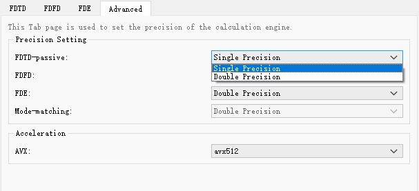
3. 计算精度调整:
将对应仿真求解器的计算精度由双精度改为单精度。
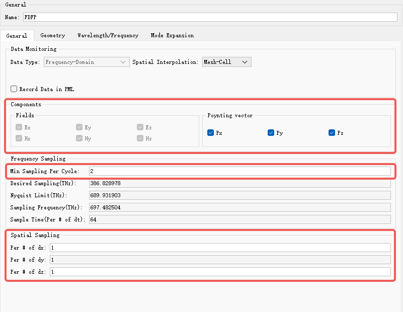
4. 监视器配置优化:
- 在仿真中,尽量使用一维或二维监视器,而不是三维监视器
- 仅记录必要的电磁场分量
- 增大时间采样间隔和空间采样步长
- 缩小记录的波段范围
5. 分析组数据后处理优化:
个别分析组的计算过程中会根据FDTD网格设置产生比较大的矩阵,可能出现内存不足的情况。优先推荐采用 Auto Nonuniform 能够大概率解决该问题,如依然内存不足,建议您联系SimWorks技术支持。
若以上调整对用户的仿真结果有较大影响,最直接的解决方案为扩容计算资源内存。