工程使用Port/Mode光源时,仿真结果截面场不是我想要的模式场? #
问题描述 #
当我使用Port或Mode光源进行仿真时,发现仿真结果与预期不符。在检查光源附近的截面场模式时,结果显示的并非我所预期的光源模式,导致无法获取准确的仿真数据。请问应如何正确设置,以确保输入的是所需的模式场?
![]()
可能的原因 #
a 用户未指定Mode/Port光源的输入模式,软件默认选取的模式与仿真目标模式不符。
b 模式求解参数设置错误。包括模式求解的波长设置错误, Use max refractive index 设置错误等。
解决方案 #
问题排查 #
Mode光源的输入模式有两种:其一为直接以基模输入(3D仿真中额外提供TE、TM基模选项);其二由用户自定义选择。若未指定光源输入模式,软件将默认采用基模输入。
Port光源需在 Port Group 属性页面中选择输入端口以及模式。端口属性页面与Mode光源的设置界面一致,若未指定端口输入,软件将按结构树顺序默认选取首个端口的首个模式作为Port光源输入。
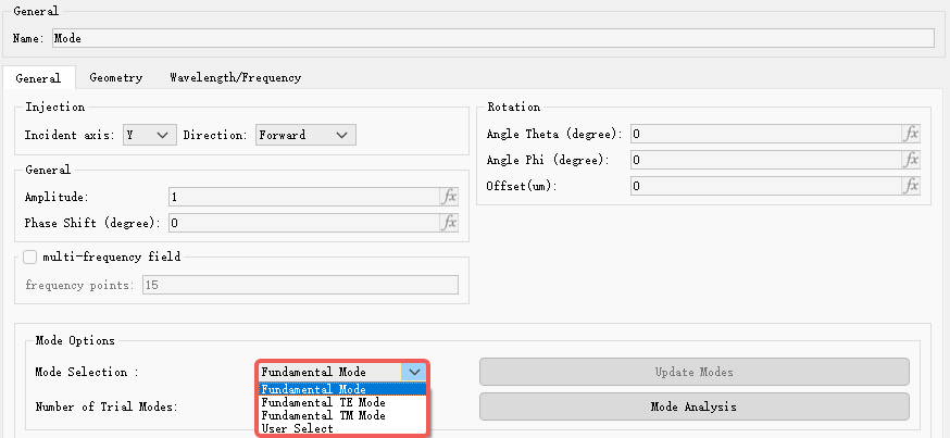
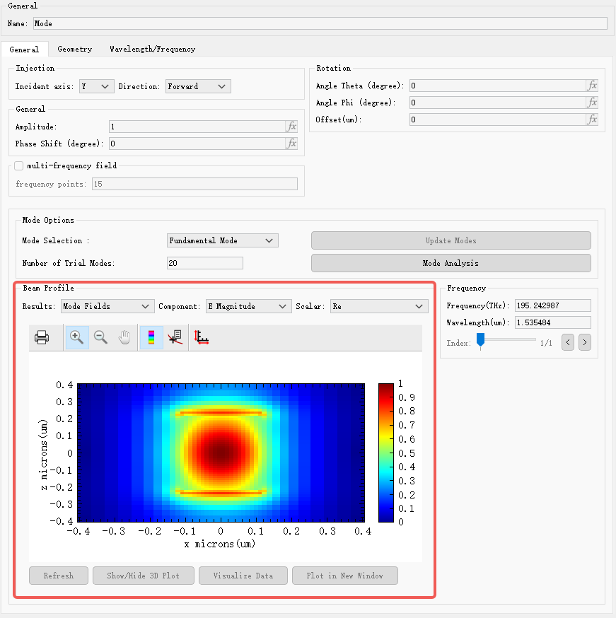
查看Mode光源属性页面,在 Mode Selection 选项中可以看到当前光源输入模式,在 Beam Profile 中可以看到输入场轮廓图,用户可以查看当前输入的模式场是否符合仿真需求。Port光源属性页面与Mode相同。
解决方法 #
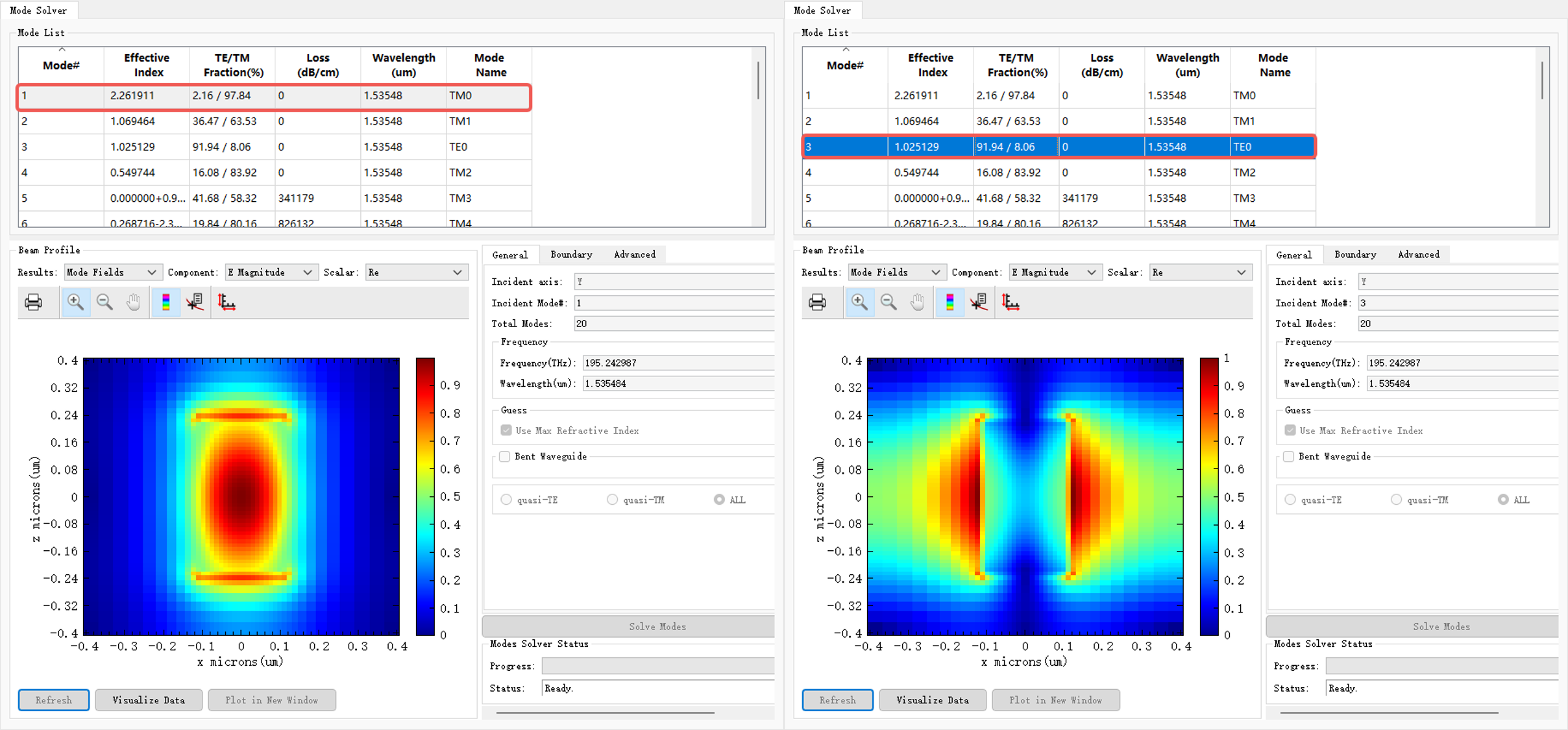
1. 对于问题 a ,将上图中 Mode Selection 选项设置为 User Select ,点击 Select Mode 进入模式选择页面。在模式求解界面中设置相关参数进行模式计算,求解结果显示默认输入模式为TM0模而非TE0模,导致仿真结果的截面场未达预期。若需使用TE0模输入,选择TE0模后重新运行仿真即可。
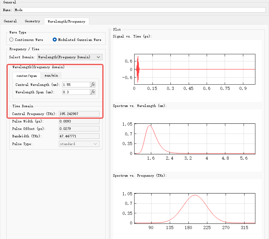
2. 对于问题 b ,用户在进入模式求解页面之前,应检查光源波长是否设置正确。模式求解将以中心频率为基准展开,中心频率的不同会显著影响模式求解的结果。
在模式求解页面中, Use max refractive index 选项为默认勾选状态,该选项使软件自动在相对折射率最大的材料附近进行模式求解。若取消勾选,则需要用户手动输入推测的有效折射率,软件将基于该值搜索接近的模态场。
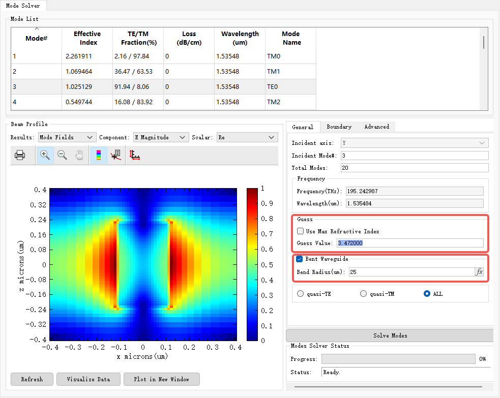
此外,用户还可以根据波导是否弯曲来配置 Bent Waveguide 参数。具体操作请参考模式光源的设置。
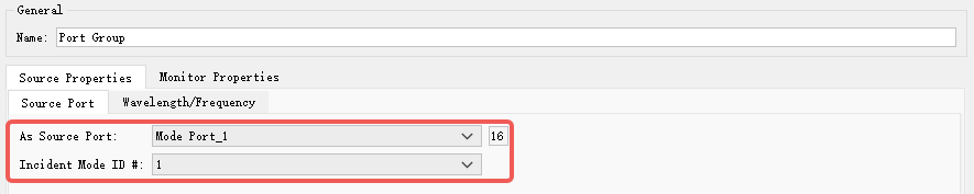
3. Port光源同理,可在 Port Group 属性中查看当前作为输入光源的端口及所选光源模式。下图显示Port_1(ID=16)作为输入光源,所选光源模式为第一个模式。注意:此时 Port Group 中除Port_1外,其他端口均作为监视器,不输入模式场。
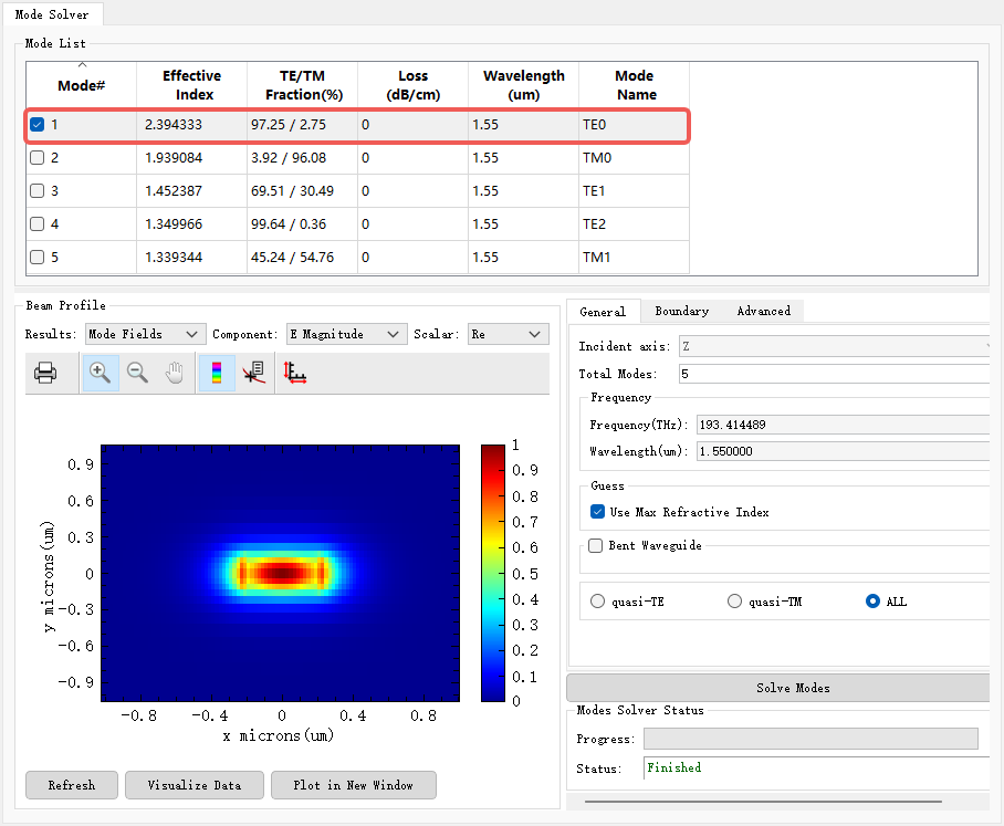
继续前往Port_1属性页面,选择 User Select 并点击 Select Mode 查看所选模式。下图可见第一个模式即为TE0模式场。
在仿真中,如果截面场结果异常,首先应检查光源输入是否符合要求,确认无误后再继续排查其他组件,例如材料设置、结构尺寸是否设置错误等等。