对象树与查看器
对象树与查看器 #
对象和对象树 #
对象与对象树 #
-
结构、求解器、自定义网格等组件都被视为一个独立的对象,而光源、监视器、端口等组件则被视为求解器的从属;
-
在软件中,对象不仅表明从属关系,还可以存储一定的结果数据;
-
在对象树中,每个对象的从属关系明确且唯一。
对象树和复合视图 #
-
对象树和复合视图是一一对应的,是对同一工程不同细节展示;
-
对象树展示各个对象之间的从属关系;
-
复合视图则展示了仿真器件的结构细节和位置关系。
更多 #
组 #
软件的对象还包括——组。
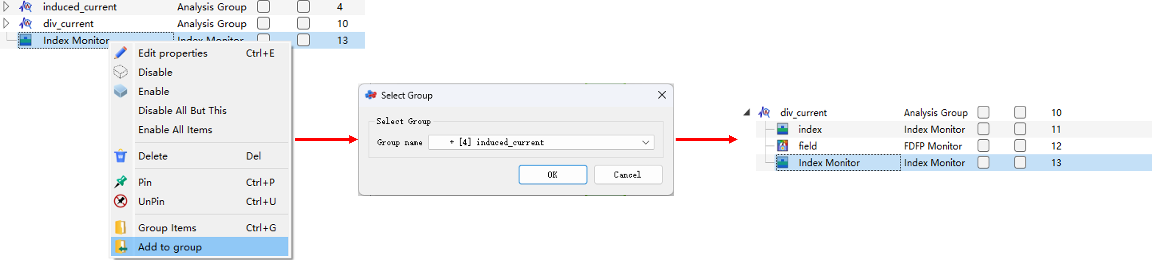
软件支持组操作,即允许将一些对象构成一个整体,用户可以将对象添加或移出组,具体操作如下:
- 将对象添加到指定组:
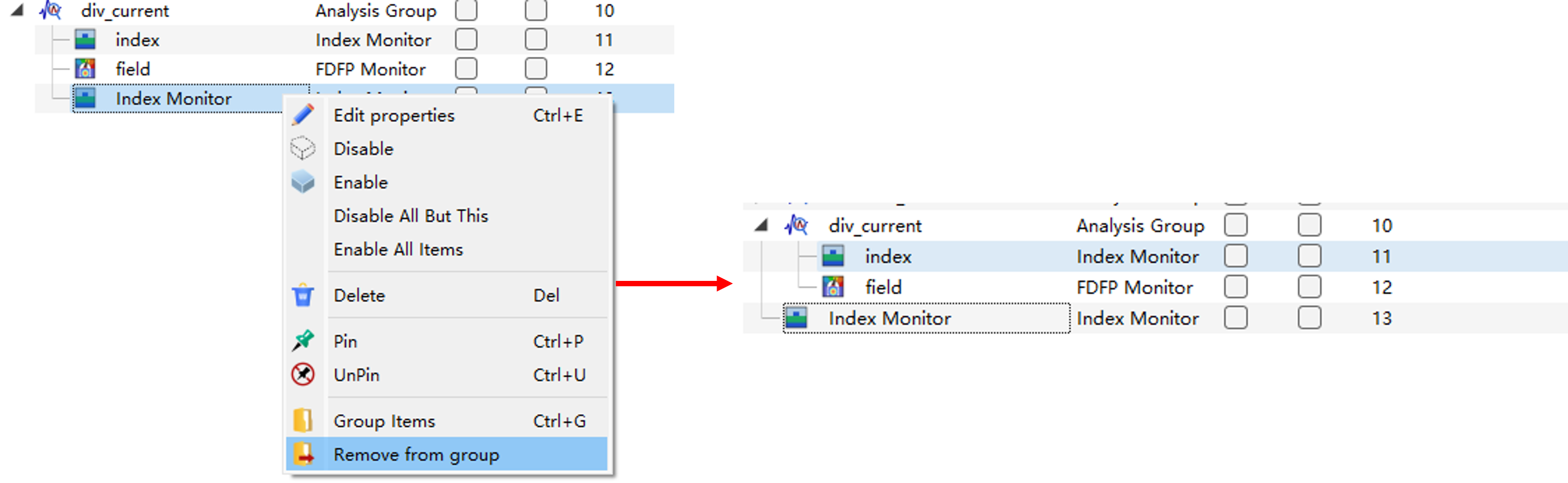
- 将对象移出组:
相对坐标和绝对坐标 #
引入组的概念后需要明确相对坐标和绝对坐标。
- 绝对坐标是相对坐标系原点的增量;
- 相对坐标是相对组坐标位置的增量。
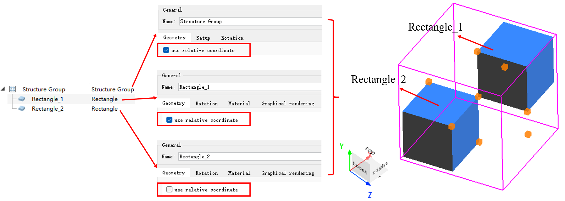
如下图所示,结构组的坐标位置设置为:ZPos=2um,XPos=2um,YPos=2um,结构组中两个结构对象设置的位置坐标相同:ZPos=−1um,XPos=1um,YPos=2um。其中结构对象Rectangle_1勾选使用相对坐标,结构对象Rectangle_2不勾选使用相对坐标。软件的复合视图显示两结构的位置不一致。即,Rectangle_2的坐标位置是相对坐标系原点,Rectangle_1的坐标位置是相对结构组的坐标位置。
对象树和深度检测 #
在View>View options>Specials标签页勾选Open graphical depth test,可对复合视图的结构图像实现深度检测。对于相同的结构组,对象树中单个结构的添加顺序不同,Open graphical depth test勾选状态不同,结构组在复合视图中显示的图像也有所差别。
| Number | Object1 | Object2 | Open graphical depth test | Viewer |
|---|---|---|---|---|
| 1 | 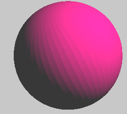 |
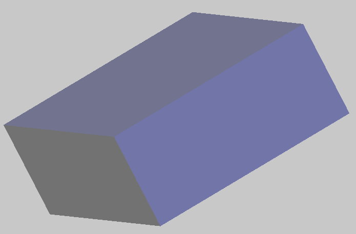 |
~ | 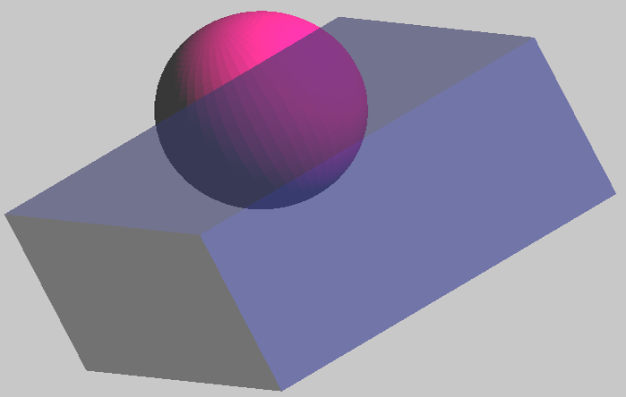 |
| 2 | |
|
~ |  |
| 3 | |
|
√ | 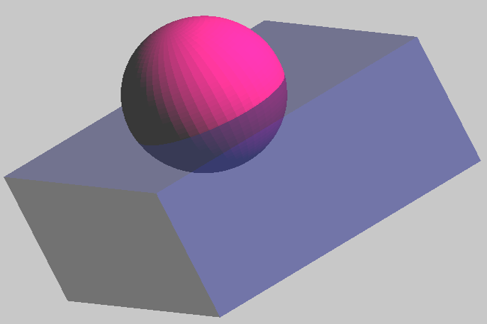 |
| 4 | |
|
√ | 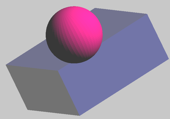 |
查看器 #
查看器提供了仿真对象的属性/数据集的快速查看功能。
点击结构树中的按钮切换为属性查看器或结果查看器。
属性查看器 #
对于结构树中的对象,当使用鼠标选中某一对象时,在查看器窗口中将显示该对象在软件中的所有参数。
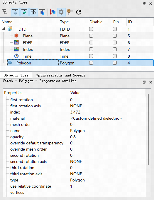
在对象属性设置中可以修改这些参数,也可以通过 get,set 脚本命令进行查看和修改。
结果查看器 #
仿真结束后,选中有结果的对象,并切换查看器为结果查看器,在查看器窗口中将显示该对象所有的原始数据。
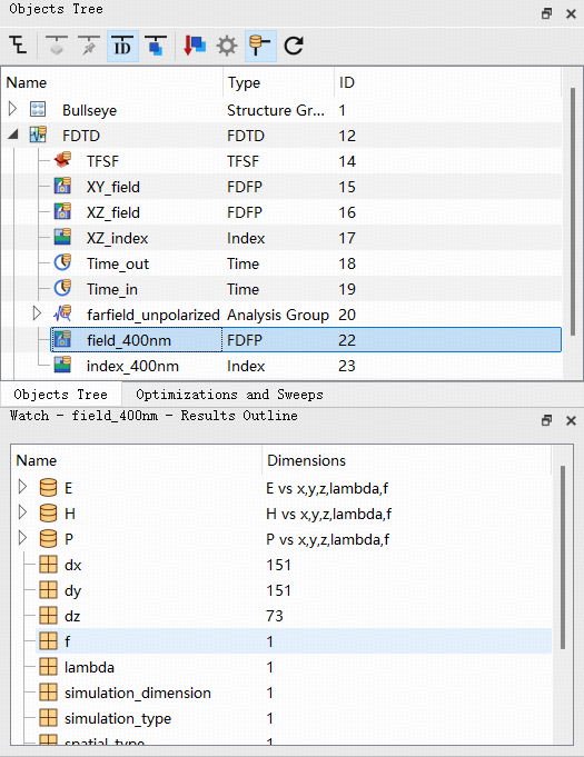
右键点击则可以将其可视化或者发送到脚本编辑器中进行下一步操作。