为什么我设置的FDFP监视器仿真结果中没有电磁场? #
问题描述 #
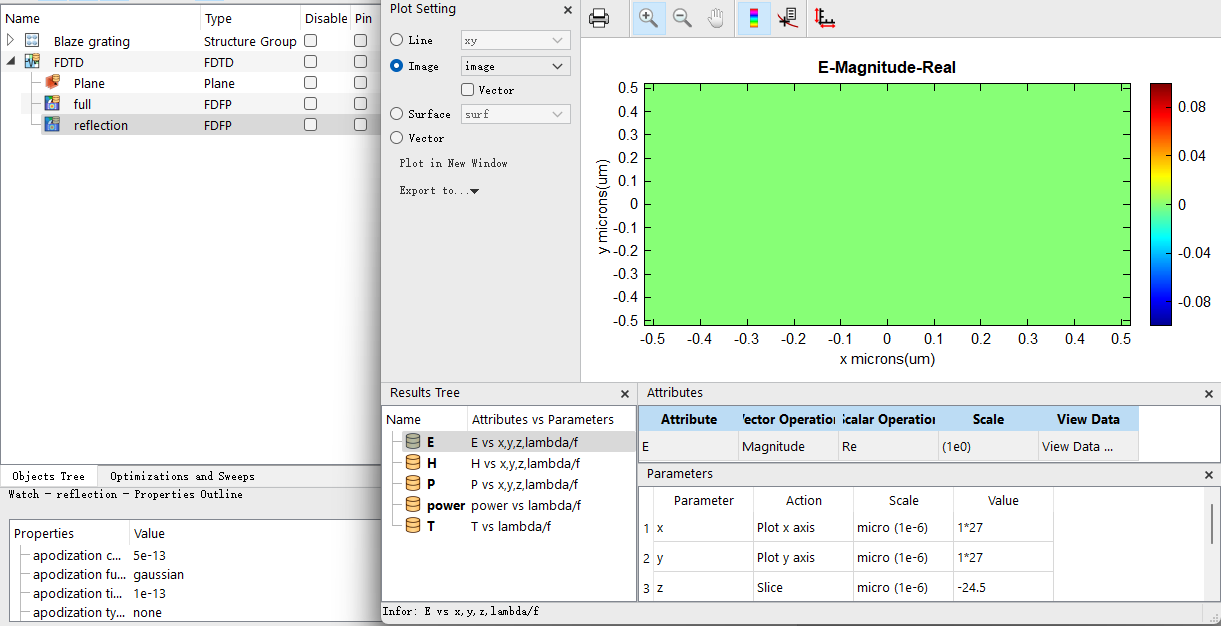
仿真完成后,我发现虽然监视器都显示有数据,但打开FDFP监视器时却看不到电磁场分布,或者电磁场强度非常微弱。这是什么原因造成的?我该如何排查和解决这个问题?
可能的原因 #
在仿真过程中,如果用户发现自己设置的FDFP监视器观察不到电磁场分布,或者电磁场强度非常微弱,可能的原因有:
1.仿真时间设置过短:仿真总时间设置过短,导致电磁场信号尚未传播到监视器所在位置,仿真便已结束。
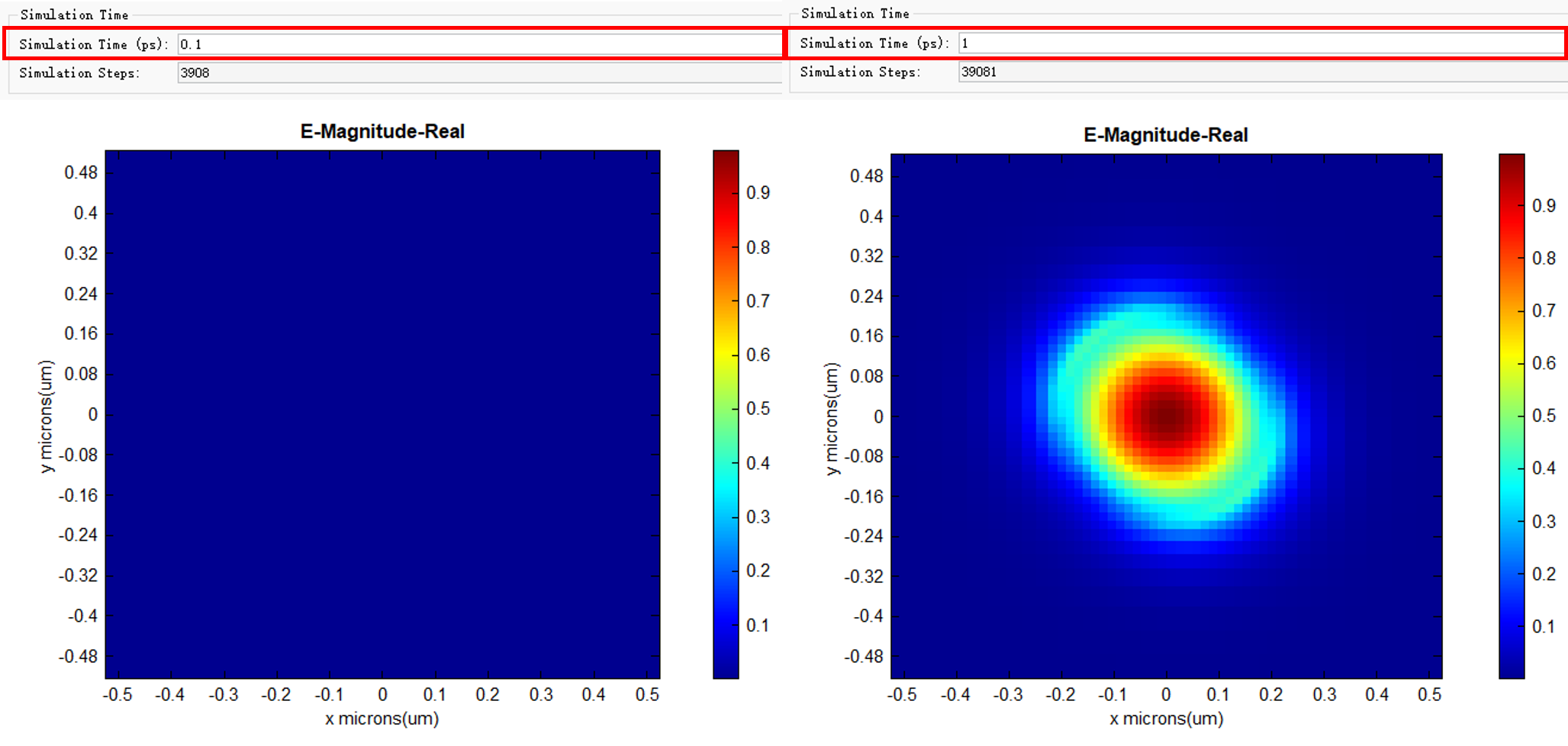
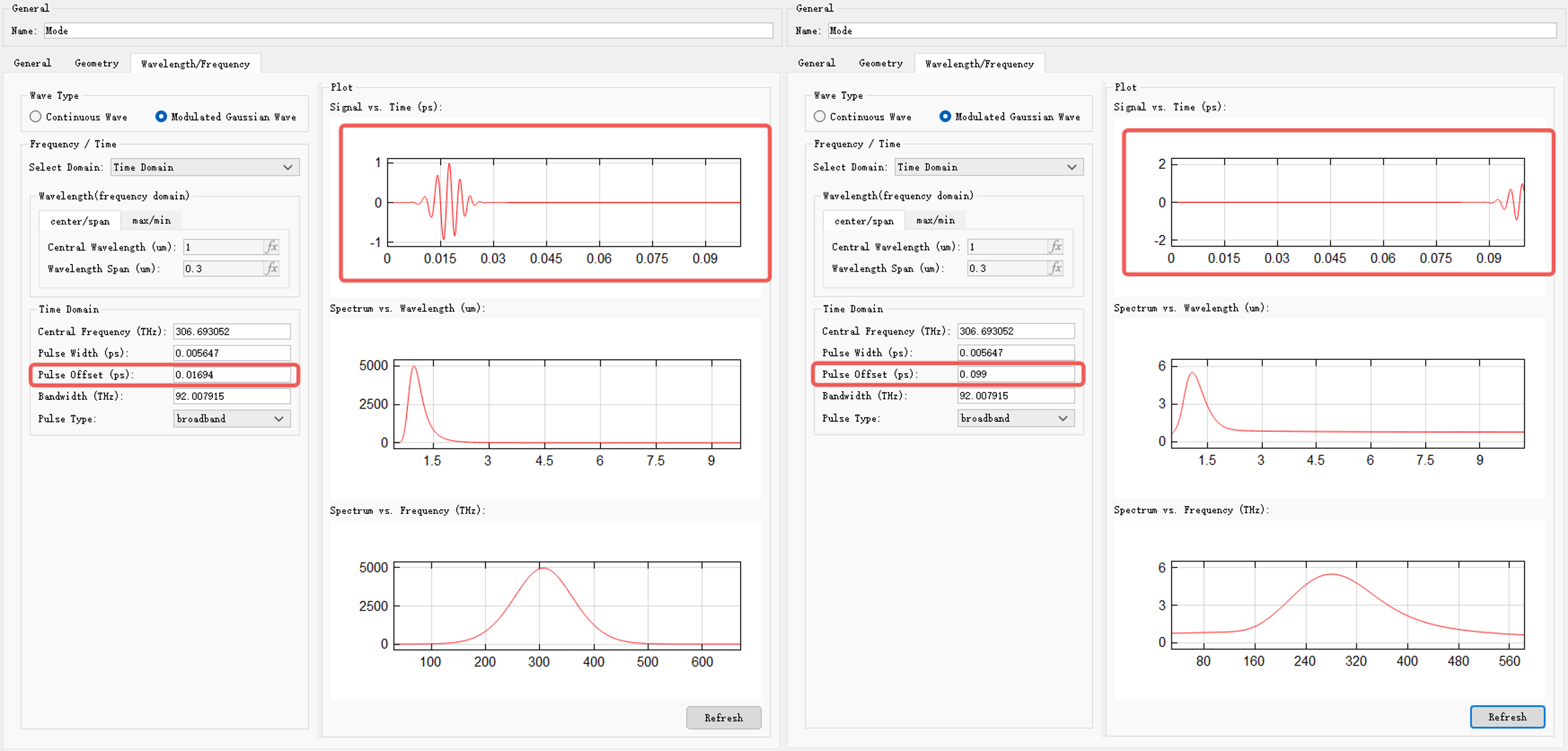
2.光源信号的 Pulse offset 设置不当:这将导致光源信号输入延迟,无法在仿真时间内及时到达监视器,甚至可能无法正常输入。如下图所示,当仿真总时间为0.1ps时,若光源延时过长,光源信号将无法完整输入。
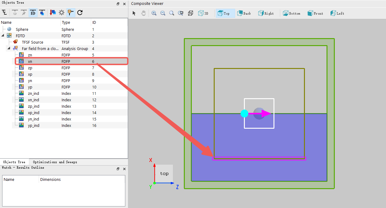
3.监视器位置设置不当:监视器未放置在仿真区域内部,导致信号未到达监视器。例如在对称性边界条件下,某些分析组内FDFP监视器将显示无结果。如需要获得对应电磁场结果,取消选择对称性边界条件即可。
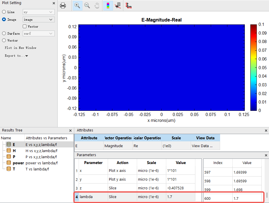
4.监视器当前展示波段能量被全部吸收:在某些仿真工程中,特定波段的光被结构或材料完全吸收,监视器在该波段将显示没有电磁场。
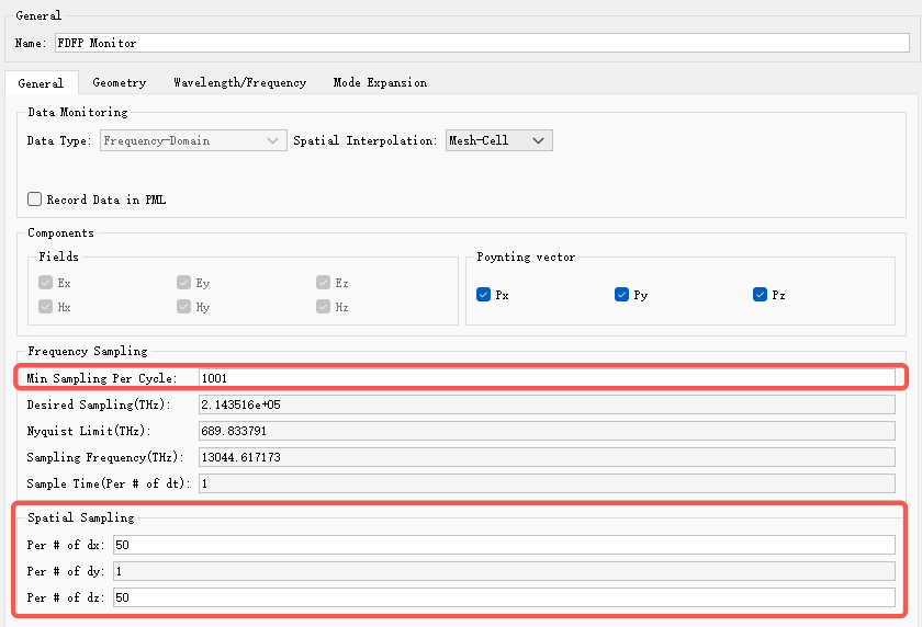
5.监视器参数设置不合理:如采样时间、采样频率、记录物理量等参数未覆盖实际仿真范围,导致监视器无法正确记录数据。
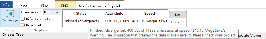
6.仿真异常终止或报错:仿真过程中出现错误或提前终止,导致监视器数据未能正常输出或者监视器数据全为NAN。例如发散等错误。
解决方案 #
问题排查 #
针对上述问题,建议按照以下方法进行排查:
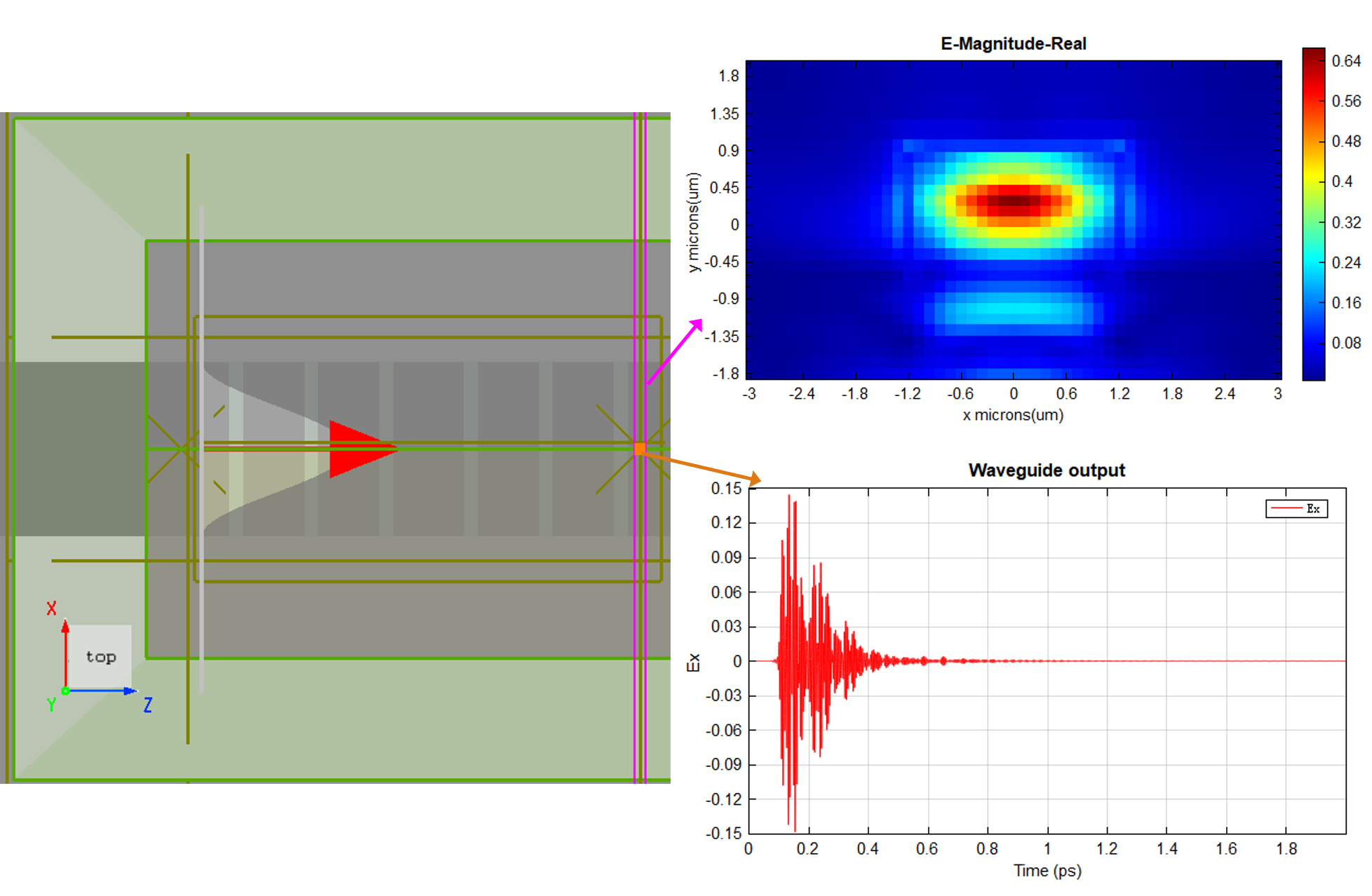
1. 检查求解器设置。仿真时间设置是否合理,能否确保电磁场有足够的时间传播到监视器的位置。用户可以在FDFP监视器附近增加一个时间监视器,以观察电磁场在该处的幅值变化,判断信号是否已到达。
2. 检查光源信号 Pulse Offset 设置是否合理,通常保持默认设置即可。用户可通过右侧的 Signal vs. Time(ps) 图像,直观观察光源信号在整个仿真时间内的输入波形,以确认信号是否按预期输入。
3. 检查监视器的位置。确认其位于仿真区域内且与光源方向、距离等设置合理。建议将监视器放置在信号传播路径上,且距离光源适中,避免信号无法到达。
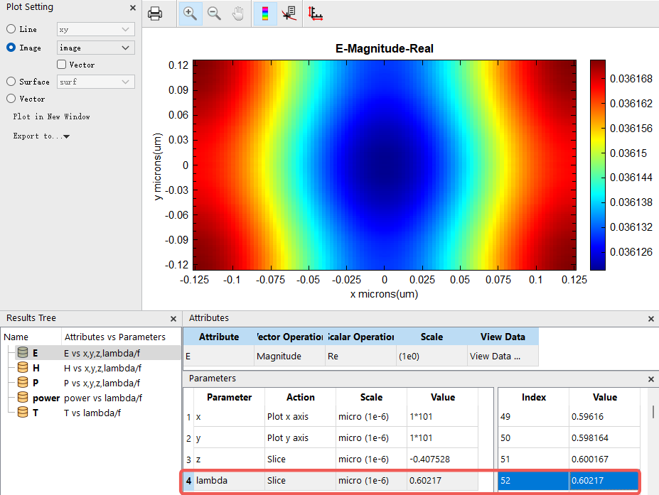
4. 检查监视器的数据结果。更改监视器展示的波长或频率范围,观察不同波长下的场分布是否都存在异常。
5. 检查监视器的设置。包括采样时间、采样步长、记录物理量等,确保与仿真需要相匹配。通常保持默认设置即可,更多信息请参考FDFP监视器的设置。
6. 如果没有看见报错窗口信息,可以查看仿真日志。以云客户端为例,一般情况下仿真日志log文件保存在C:\Users\AppData\Local\SimWorks Photonic Finite Difference Lite Client\logs。
解决方法 #
对于问题1,适当增加仿真时间或步数,确保电磁场有足够时间传播到监视器的位置。一般建议用户将仿真总时间设置得足够长,以便仿真能够通过 Early Shutoff 自动结束。
对于问题2,将光源的 Pulse offset 设置得足够小,避免信号输入延时。与问题1类似,建议这两项设置互相参照,使仿真能够通过 Early Shutoff 来自动停止。
对于问题3,调整监视器位置,确保其处于信号传播路径上且距离光源适中。
对于问题4,在监视器中选择合适的波长或频率范围,避免因波段选择不当导致无数据显示。
对于问题5,合理设置监视器参数,如采样时间、采样频率、记录物理量等,确保能够记录所需数据。
对于问题6,如仿真出现报错,建议根据报错信息排查模型设置、材料参数、边界条件等问题。必要时请联系技术支持。
如果经过上述方法仍未能解决问题,建议将具体工程文件和设置截图反馈给技术支持团队,以便获得更详细的帮助。