牛眼孔径
前言
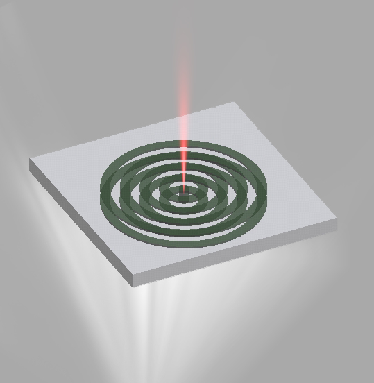
牛眼孔径是一种金属亚波长光学结构,其特征为中央圆孔与周期性分布的同心环形沟槽。当入射光照射到金属表面时,环形沟槽通过散射作用将部分入射光耦合为沿表面传播的表面等离激元(SPP)。这些SPP在传播过程中相互干涉,并在满足相位匹配条件的波长下在中央孔径处产生相干汇聚,使孔径内局域电场显著增强,从而实现强透射与波长选择性增强效应。该结构广泛应用于等离激元传感、光耦合器件以及高指向性辐射天线等领域。本案例对银薄膜上的牛眼孔径结构进行仿真,展示其典型的光场增强与定向辐射效应。
仿真设置
结构设置
附件工程中包含一个 bullseye 结构组,用于构建仿真模型。其中银薄膜的厚度为 ,中心孔径的半径为 ,完全贯穿银层。在银薄膜的上下表面各刻蚀了四个深度为 ,宽度为 的同心圆沟槽,沟槽的周期为 。
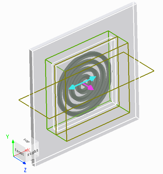
光源设置
仿真采用波长范围为 的总场散射场光源,从结构的下表面入射。由于该结构不具有周期性,FDTD 在 方向上使用 边界条件。直接使用普通平面波光源会导致靠近 边界的电场出现衍射和边缘效应,从而无法维持理想的平面传播。采用 TFSF 光源可以有效避免此类边界干扰,同时在结构内部形成理想的平面波入射场。
为了获得非偏振结果,通常需要运行两个正交极化方向的仿真。但由于牛眼结构具有中心对称性,可以在单次仿真中,通过将结果与自身转置相加来得到非偏振远场结果,从而简化计算。
仿真结果
为了分析牛眼结构对于透射率的影响,需要进行两次仿真:一次包含同心圆沟槽,一次不包含同心圆沟槽。在 bullseye 结构组中,通过设置变量 make_grooves 为0或1来取消或者添加同心圆沟槽,从而方便比较两种结构的透射行为。
远场透射率
使用附件中的 sp_bulleye_analysis.msf 脚本文件,可自动运行两次仿真:一次包含同心圆沟槽结构,一次仅保留中央孔径。比较含沟槽与不含沟槽结构的远场透射率谱,并绘制对比图,如下所示。

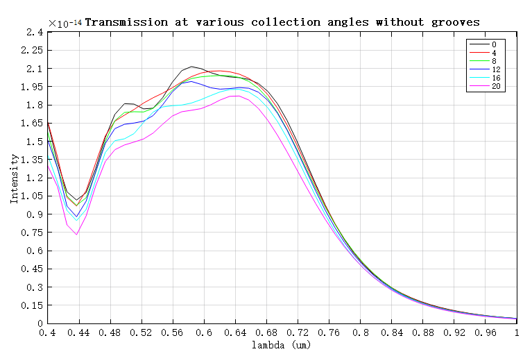
当仿真包含同心圆沟槽时,透射光主要集中在约 的波长处,表现出明显的波长选择性,峰值透射率为 ;而在不包含同心圆沟槽的情况下,同一波长处的透射率仅为 。由此可见,沟槽结构使透射率提高约三个数量级,充分体现了牛眼孔径在特定波长下的光场增强效应。
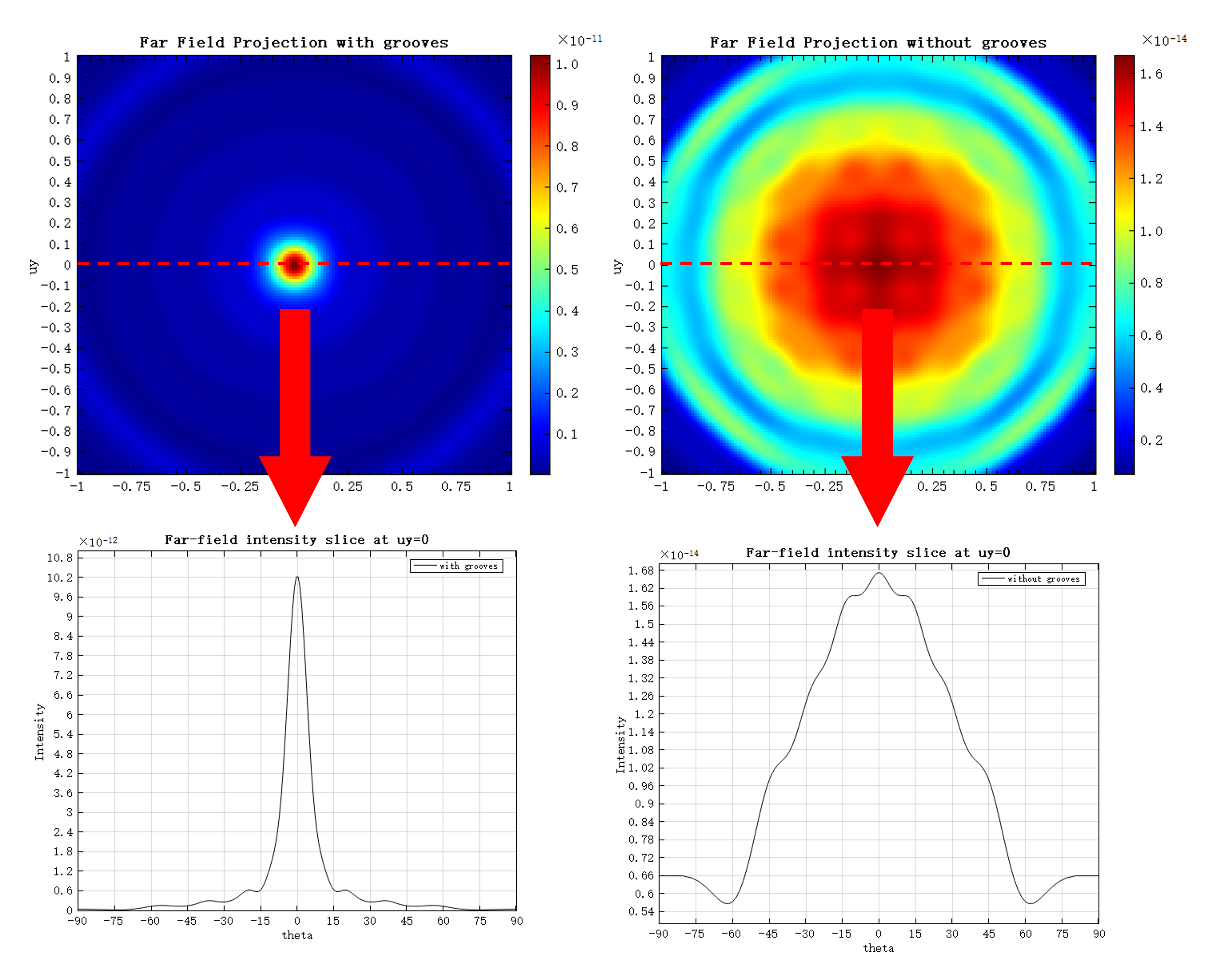
远场辐射角分布
在透射峰值对应的波长处,脚本进一步计算了远场辐射强度分布,如下图所示。可以看出,当结构包含同心圆沟槽时,透射光更为集中,发散角约为 ;而在不包含沟槽的情况下,发散角约为 。